@]
VIDEO
OUT
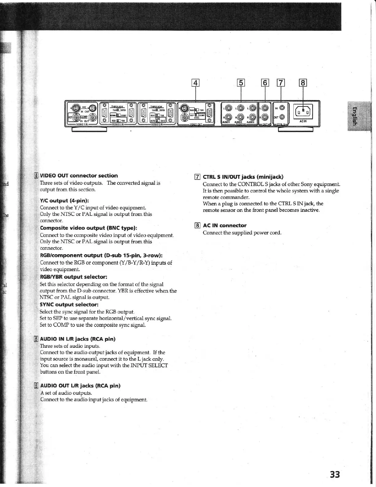
connector section
Three sets of video outputs. The converted signal
is
output from this section.
VIC
output
(~pin):
Connect to the Y
IC
input of video equipment.
Only the
NTSC
or PAL signal
is
output
from this
co
nnector.
Composite
video
output
(BNC
type)
:
Connect to the composite video
input
of video equipment.
Only the
NTSC
or PAL signal is
output
from this
connector.
RGB/component
output
(D-sub 15-pin.
3-row):
Connect to the
RGB
or component
(Y
IB-
Y
IR
-
Y)
inputs of
video equipment.
RGBIYBR
output
selector:
Set
this selector depending on the format of the signal
output from the
D·sub connector.
YER
is effective
when
the
N1SC or PAL signal is output.
SYNC
output
selector:
Select the sync signal for the
RGB
output.
Set
to
SEP
to
use separate horizontal/vertical sync signal.
Set
to COMP to use the composite sync signal.
lID
AUDIO IN
UR
jacks
(RCA
pin)
Three sets of audio inputs.
Connect to the audio
output
jacks of equipment.
If
the
input source
is monaural, connect
it
to the L jack only.
You
can select the audio input with the INPUT SELECT
buttons .
on
the front panel.
lID
AUDIO OUT
LlR
jacks
(RCA
pin)
A set of audio outputs.
Connect to the audio
input
jacks of equipment.
III CTRL 5 IN/OUT
jacks
(minijack)
Connect to the CONTROL 5 jacks of other Sony equipment.
It
is
then possible to control the whole system with a single
remote corrunander.
When a plug
is connected to the CI'RL S IN jack, the
remote sensor on the front panel becomes inactive.
[ID
AC IN connector
Connect the supplied power cord.
33
1