HBD-E2100/E3100/E3200/E4100/E6100
33
SECTION 5
TROUBLESHOOTING
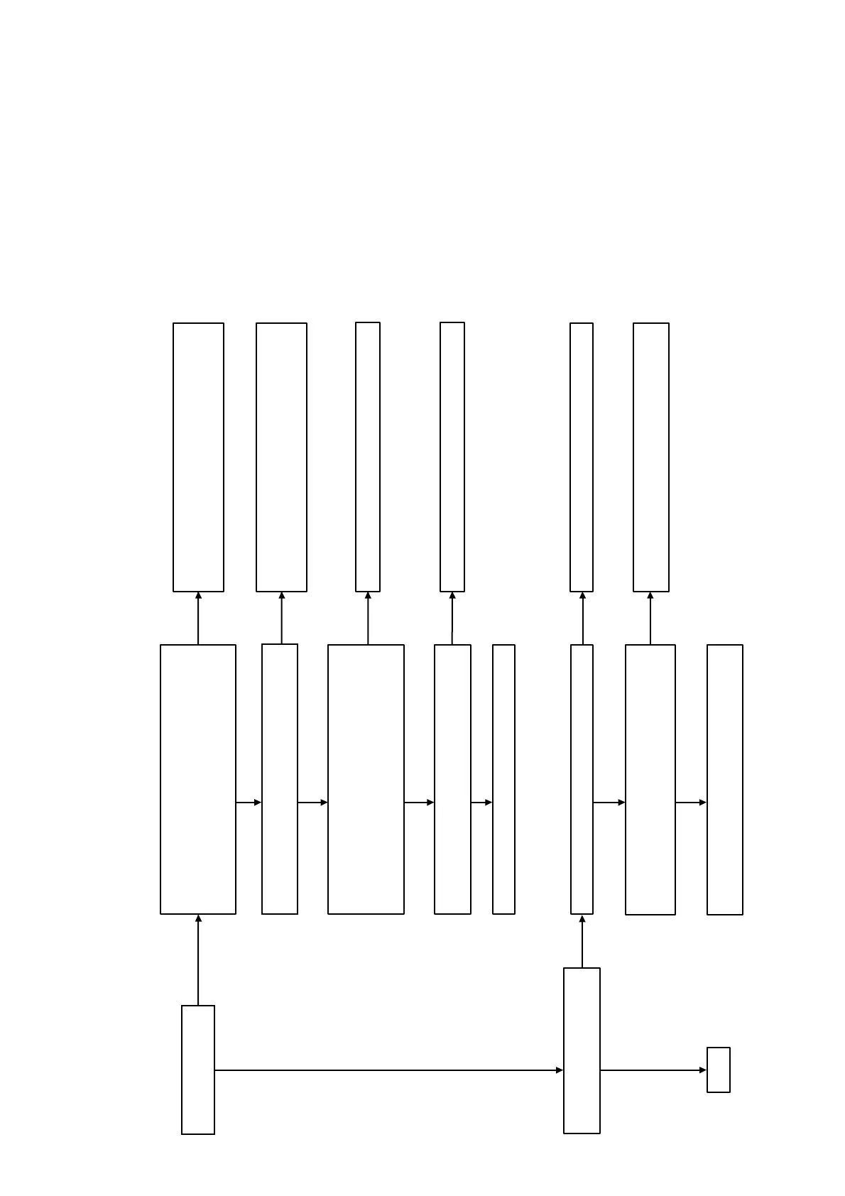
Power Check Flow (1/2)
Check that the output voltages of the switching regulator
(SWR1) are the following value.
CN301 pin 1: 12 V (FEUNSW12V)
CN301 pin 2: 12 V (ICUNSW12V)
CN301 pin 3: 12 V (UNSW12V)
Check that the following fuses and thermistor are not damaged.
TH802/F802/F201/F202/F203
Yes
Yes
Check each voltage with reference to the schematic diagrams,
and check that there is no problem in them.
Check the related IC on the MB1002 board.
Yes
Check the following power control signal in the power on state.
(Normally voltage: +3.3 V)
MB1002 board IC801 pin 36 to 38
(PCONT1 to PCONT3)
Pin 25 (PCONT_FL)
Yes
The power is turned on.
A
No
Yes
Protect mode happened “PROTECT”
display appears on fluorescent tube.
No
Yes
Check that harness is inserted normally at CN101
Remove harness of CN101, CN4, FFC CN3505.
Measure switching supply board CN101 pin4 <-> pin1,
(normal voltage > 30V)
Yes
Yes
AMP board damage.
Exchange the complete AMP board.
Check that harness is inserted normally at CN301 and
CN202. When harness is inserted normally, exchange the
switching regulator (SWR1).
No
Exchange the damaged fuse or thermistor. Exchange the
complete MB1002 board, when the power is not turned on,
even if you exchange fuses.
No
Power supply IC is damaged. Exchange the power supply IC.
No
Exchange the complete MB1002 board.
No
No
Insert normally the harness and power ON again.
No
Switching supply board damage. Exchange the complete
switching supply board.
Ver. 1.5