HCD-ECL77BT/ECL99BT
HCD-ECL77BT/ECL99BT
1717
SECTION 4
ELECTRICAL CHECK
CD SECTION
Note:
1. CD block is basically constructed to operate without adjustment.
2. Use YEDS-18 disc (Part No. 3-702-101-01) unless otherwise indicat-
ed.
3. Use an oscilloscope with more than 10 M impedance.
4. Clean the object lens by an applicator with neutral detergent when the
signal level is low than specifi ed value with the following check.
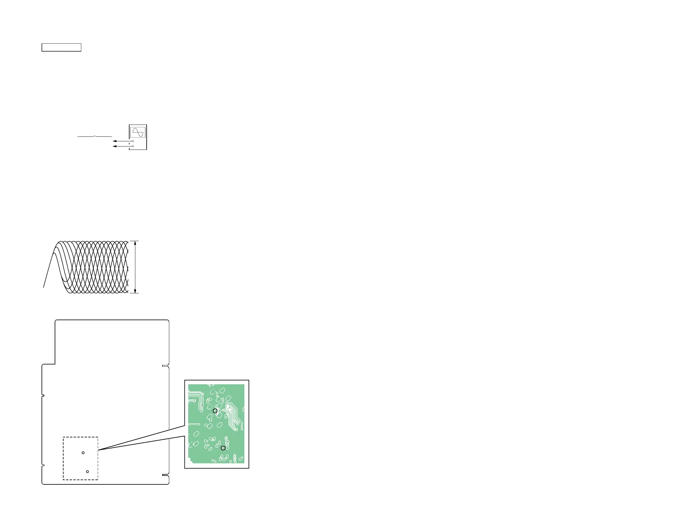
RF SIGNAL CHECK
+
–
MAIN board
TP27 (PUHRF)
TP31 (VREF1)
oscilloscope
(DC range)
Procedure:
1. Connect the oscilloscope to TP27 (PUHRF) and TP31
(VREF1) on the MAIN board.
2. Press the [
?
/
1
] button to turn the power on.
3. Press the [FUNCTION] button to turn the CD function.
4. Press the [
Z
] button to open the disc tray.
5. Set the disc (YEDS-18) on the disc tray.
6. Press the [
Z
] button to close the disc tray.
7. Press the [
u
] button to playback.
8. Confi rm that oscilloscope waveform is as shown in the fi gure
below. (eye pattern)
A good eye pattern means that the diamond shape () in the
center of the waveform can be clearly distinguished.
VOLT/DIV: 200 m
TIME/DIV: 400 ns
level: 1.2 ± 0.2 Vp-p
Connection Location:
– MAIN Board (Conductor Side) –
TP31
(VREF1)
TP27
(PUHRF)
TP31
(VREF1)
TP27
(PUHRF)