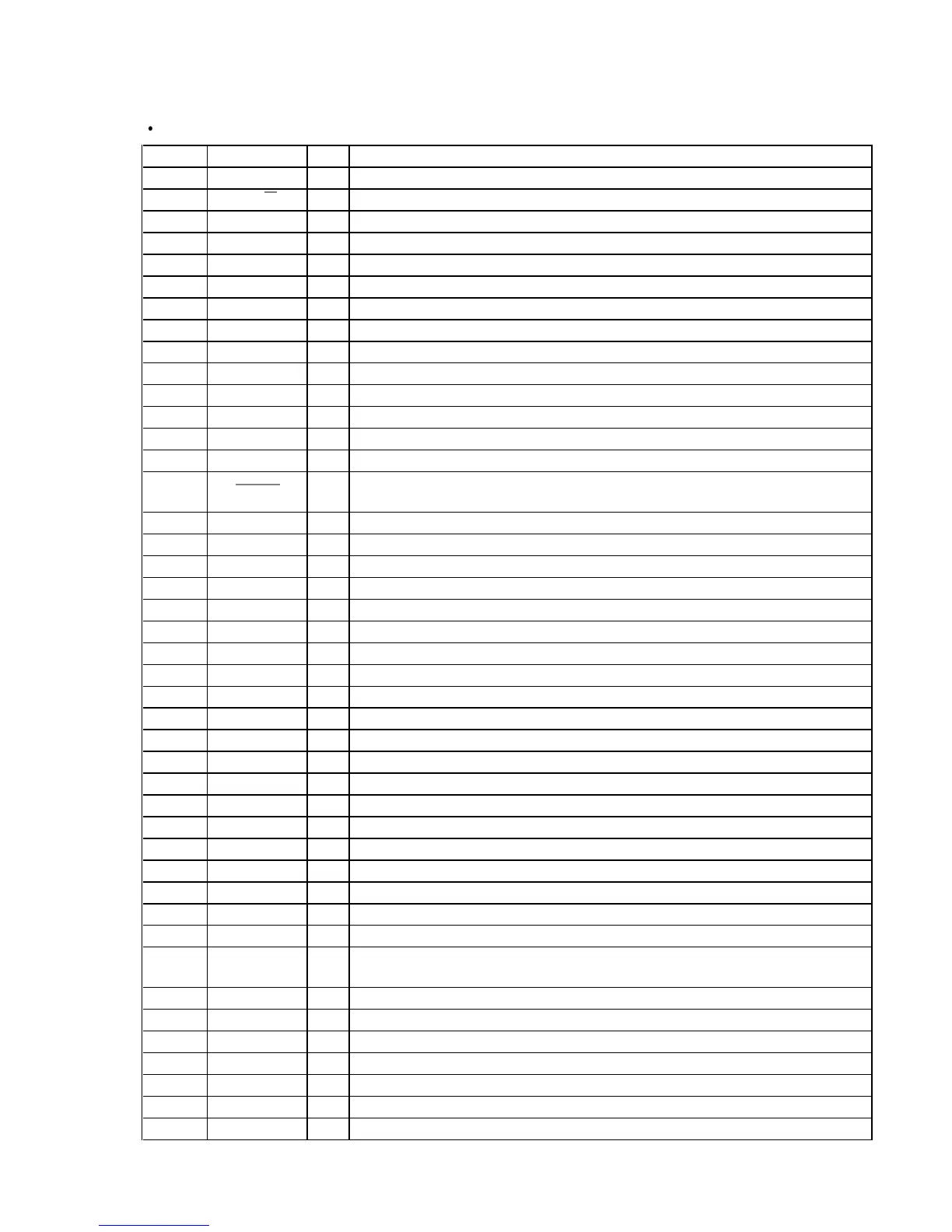
MAIN BOARD IC301 µPD780016YGF-015-3BA (MASTER CONTROLLER)
Pin No. Pin Name I/O Function
1 TA-MUTE O
Line mute control signal output terminal “L”: mute on
DBFB normal/high selection signal output terminal “L”: DBFB high, “H”: DBFB low
Serial data latch pulse output to the electrical volume (IC201)
Serial data latch pulse output to the key control (IC1401)
On/off selection signal output of the key control circuit “L”: on
Relay drive signal output for the main speaker (front speaker) “H”: on
Relay drive signal output terminal Not used (open)
Relay drive signal output terminal Not used (open)
Main system clock output terminal (5 MHz)
Main system clock input terminal (5 MHz)
Power supply terminal (+5V)
Sub system clock output terminal (32.768 kHz)
Sub system clock input terminal (32.768 kHz)
System reset signal input from the reset signal generator (IC302) “L”: reset For several
hundreds msec. after the power supply rises, “L” is input, then it changes to “H”
Subcode sync (S0+S1) detection signal input terminal Not used (fixed at “L”)
Output terminal for the software test (open)
AC off detection signal input from the reset signal generator (IC302)
Serial data reading clock signal input for the radio data system Not used (fixed at “L”)
Serial data input for the radio data system Not used (open)
Power supply terminal (+5V)
Power supply terminal (+5V) (for A/D conversion)
Setting terminal for the test Normally: “H”
Shut off detection signal input from the deck-A reel pulse detector (Q1001)
Shut off detection signal input from the deck-B reel pulse detector (Q1002)
Detection input from the deck-B half detect switch (S1007)
Setting terminal for the version
Setting terminal for the test Normally: “L”
Setting terminal for the demonstration H/L Fixed at “L”
Ground terminal (for A/D conversion)
Sub-code Q data input terminal Not used (fixed at “L”)
Power on/off selection signal output for the CD digital out optical “H”: power on
Not used (open)
Setting terminal for the function 1 Fixed at “L”
Setting terminal for the function 2 Fixed at “L”
Serial data latch pulse output terminal Not used (open)
Serial data latch pulse output terminal Not used (open)
Serial data input terminal Not used (fixed at “L”)
6-1. IC PIN FUNCTION DESCRIPTION
SECTION 6
DIAGRAMS
 Loading...