19
4. Mode: Record
5. Mode: Playback
6. Confirm playback the signal recorded in step 3 become
adjustable level as follows.
If these levels do not adjustable level, adjustment the RV301
(L-CH) and RV351 (R-CH) on the MAIN board to repeat steps
4 and 5.
Adjustable Level:
CN301 PB level: 47.2 to 53.0 mV (–24.3 to –23.3 dB)
Adjustment Location: MAIN board
[MAIN BOARD] (Component Side)
[LEAF SW BOARD]
(Conductor Side)
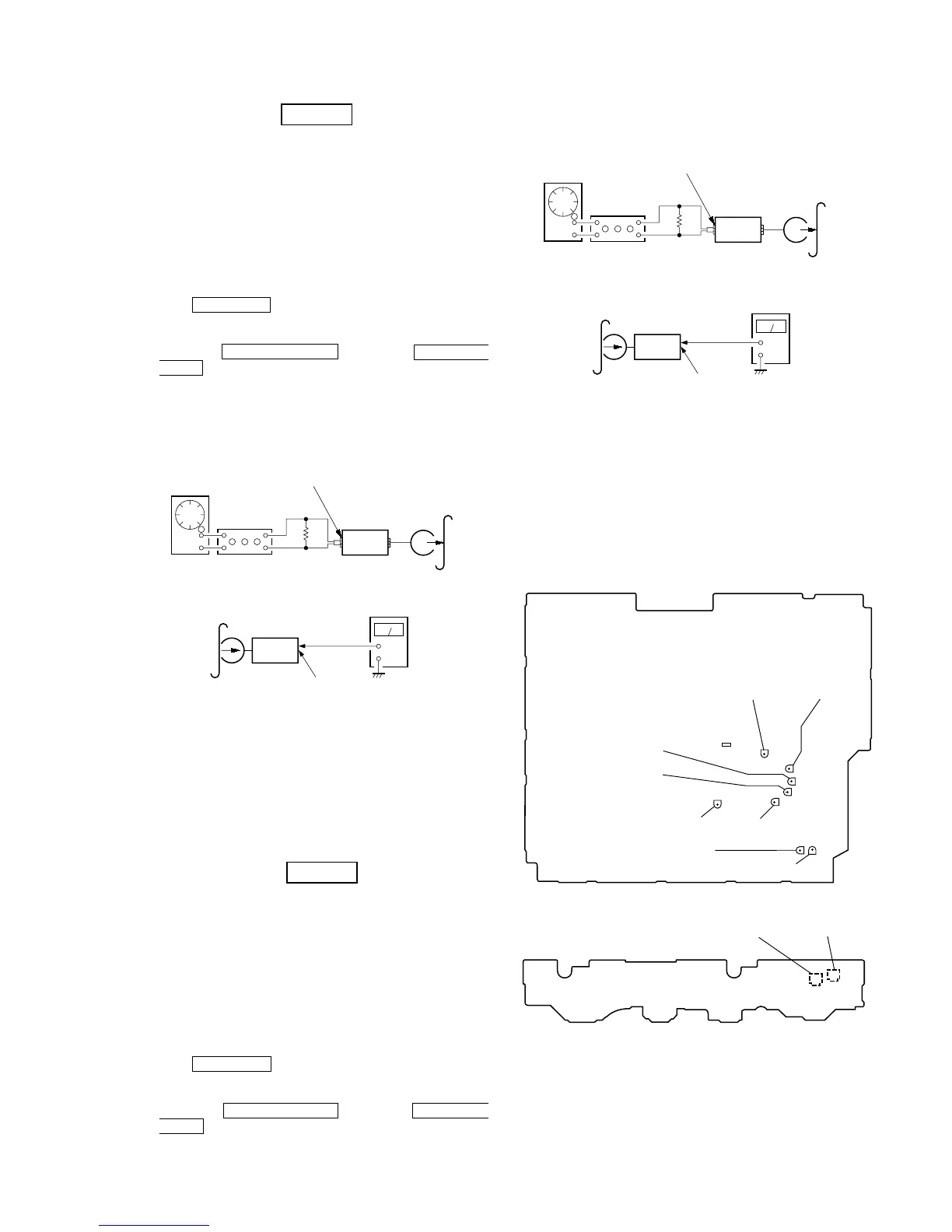
REC Bias Adjustment DECK B
Procedure:
INTRODUCTION
When set to the test mode performed in Tape Speed Adjustment,
when the tape is rewound after recording, the “REC memory mode”
which rewinds only the recorded portion and playback is set.
This “REC memory mode” is convenient for performing this
adjustment. During recording, the input signal FUNCTION will
automatically switch to VIDEO.
(If do not operation of stopped from recording complete, and rotate
of shuttle knob then rewind to recording start position.)
1. Press MD (VIDEO) button to select VIDEO. (This step is not
necessary if the above test mode has already been set.)
2. Insert a tape into deck B.
3. After press REC PAUSE/START button, press REC PAUSE/
START button, then recording start.
4. Mode: Record
5. Mode: Playback
6. Confirm playback the signal recorded in step 3 become
adjustable level as follows.
If these levels do not adjustable level, adjustment the RV304
(L-CH) and RV354 (R-CH) on the AUDIO board to repeat steps
4 and 5.
Adjustable Level: Playback output of 315 Hz to playback output
of 10 kHz: ±1.0 dB
Adjustment Location: MAIN board
REC Level Adjustment
DECK B
Procedure:
INTRODUCTION
When set to the test mode performed in Tape Speed Adjustment,
when the tape is rewound after recording, the “REC memory mode”
which rewinds only the recorded portion and playback is set.
This “REC memory mode” is convenient for performing this
adjustment. During recording, the input signal FUNCTION will
automatically switch to VIDEO.
(If do not operation of stopped from recording complete, and rotate
of shuttle knob then rewind to recording start position.)
1. Press MD (VIDEO) button to select VIDEO. (This step is not
necessary if the above test mode has already been set.)
2. Insert a tape into deck B.
3. After press REC PAUSE/START button, press REC PAUSE/
START button, then recording start.
attenuator
set
MD/VIDEO (AUDIO) IN
1) 315 Hz
2) 10 kHz
50 mV (–23.8 dB)
600 Ω
blank tap