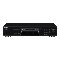
— 63 —
Pin No. I/O DescriptionPin Name
• Abbreviation
EFM : Eight to Fourteen Modulation
PLL : Phase Locked Loop
* (3) of I/O is 3-state output, (A) is analog output.
41
42
43
44
45
46
47
48
49
50
51
52
53
54
55
56
57
58
59
60
61
62
63
64
65
66
67
68
69
70
71
72
73
74
75
76
77
78
79
80
WFCK
GTOP
GFS
XPLCK
EFMO
RAOF
MVCI
TEST2
DIPD
DVSS
DICV
DIFI
DIFO
AVDD
ASYO
ASYI
BIAS
RFI
AVSS
CLTV
PCO
FILI
FILO
PEAK
BOTM
ABCD
FE
AUX1
VC
ADIO
TEST3
AVDD
ADRT
ADRB
AVSS
SE
TE
AUX2
DCHG
APC
O
O
O
O
O
O
I
I
O (3)
—
I (A)
I (A)
O (A)
—
O
I (A)
I (A)
I (A)
—
I (A)
O (3)
I (A)
O (3)
I (A)
I (A)
I (A)
I (A)
I (A)
I (A)
O (A)
I (A)
—
I (A)
I (A)
—
I (A)
I (A)
I (A)
I (A)
I (A)
WFCK clock (7.35 kHz) signal output
(Playback: EFM decoder PLL Recording: EFM encoder PLL)
“H”: Opens playback EFM frame sync protection window
“H”: Playback EFM sync and interpolation protection timing match
EFM decoder PLL clock output (98 fs=4.3218 MHz)
Falling edge and EFM signal edge match
EFM signal output (Recording)
Internal RAM overflow detection signal output (decoder monitor output)
Outputs “H” when the disc rotation exceeds ±4F jitter margin during playback
Digital-in PLL oscillation input (Not used) (Fixed at “L”)
Test pin (Fixed at “L”)
Digital-in PLL phase comparison output
Internal VCO: (Frequency: Low n “H”) External VCO: (Frequency: Low n “L”)
Ground (Digital)
Digital-in PLL internal VCO control voltage input
Filter input when digital-in PLL internal VCO is used
Filter output when digital-in PLL internal VCO is used (Not used)
Power supply (+5V) (Analog )
Playback EFM full-swing output (L=VSS, H=VDD)
Playback EFM asymmetry comparate voltage input
Playback EFM asymmetry circuit constant current input
Inputs playback EFM RF signal from RF amplifier
Ground (Analog )
Decoder PLL master clock PLL VCO control voltage input
Decoder PLL master clock PLL phase comparison output
Decoder PLL master clock PLL filter input
Decoder PLL master clock PLL filter output
Inputs peak hold signal for light amount signal from RF amplifier
Inputs bottom hold signal for light amount signal from RF amplifier
Light amount signal from RF amplifier
Input of focus error signal from RF amplifier
Input of auxiliary signal from RF amplifier
Input of middle point voltage (+2.5V) from RF amplifier
A/D converter input signal monitor output
Test input (Fixed at “L”)
Power supply (+5V) (Analog)
A/D converter operation range upper limit voltage input (Fixed at “H”)
A/D converter operation range lower limit voltage input (Fixed at “L”)
Ground (Analog)
Input of sled error signal from RF amplifier
Input of tracking error signal from RF amplifier
Auxiliary input pin 2 (Fixed at “L”)
Connected to ground
Laser APC input (Fixed at “L”)
 Loading...