39
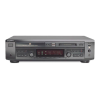
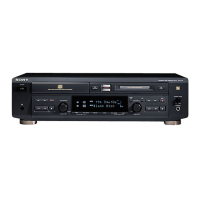
MXD-D40
9. Press the [YES] button to display “EFB = MO-P”.
Then, the optical pick-up moves to the pit area automatically
and servo is imposed.
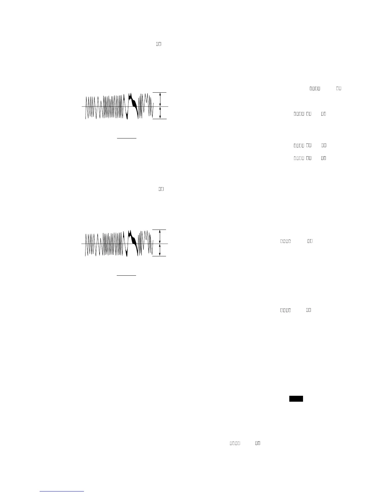
10. Observe the waveform of the oscilloscope, and check that the
specified value is satisfied. Do not turn the [ AMS ]
(MD) knob.
Traverse Waveform
11. Press the [YES] button to display “EF MO CHECK (C14)”.
The disc stops rotating automatically.
12. Press the [ EJECT] button and take out the disc.
13. Load the check disc (MD) TDYS-1.
14. Turn the [ AMS ] (MD) knob and display “EF CD
CHECK” (C15).
15. Press the [YES] button to display “EFB = CD”. Servo is
imposed automatically.
16. Observe the waveform of the oscilloscope, and check that the
specified value is satisfied. Do not turn the [ AMS ]
(MD) knob.
Traverse Waveform
17. Press the [YES] button to display “EF CD CHECK” (C15).
18. Press the [ EJECT] button and take out the check disc (MD)
TDYS-1.
Check Location: BD (MD) board (see page 44)
lL
lL
lL
A
A
6-7. Focus Bias Check
Change the focus bias and check the focus tolerance amount.
Checking Procedure:
1. Load the test disk (MDW-74/GA-1).
2. Turn the [ AMS ] (MD) knob to display “CPLAY2
MODE” (C36).
3. Press the [YES] button to display “CPLAY2MID”.
4. Press the [MENU/NO] button when “C = AD = ” is
displayed.
5. Turn the [ AMS ] (MD) knob to display “FBIAS
CHECK” (C16).
6. Press the [YES] button to display “ / c = ”.
The first four digits indicate the C1 error rate, the two digits
after [/] indicate ADER, and the 2 digits after [c =] indicate
the focus bias value.
Check that the C1 error is below 20 and ADER is below 2.
7. Press the [YES] button to display “ / b = ”.
Check that the C1 error is about 100 and ADER is below 2.
8. Press the [YES] button to display “ / a = ”.
Check that the C1 error is about 100 and ADER is below 2.
9. Press the [MENU/NO] button, then press the [ EJECT] button
and take out the test disc.
6-8. C PLAY Check
MO Error Rate Check
Checking Procedure:
1. Load the test disk (MDW-74/GA-1).
2. Turn the [ AMS ] (MD) knob to display “CPLAY2
MODE” (C36).
3. Press the [YES] button to display “CPLAY2MID”.
4. The display changes to “C = AD = ”.
5. If the C1 error rate is below 20, check that ADER is 00.
6. Press the
[MENU/NO] button to stop playback, then press the
[ EJECT] button and take out the test disc.
CD Error Rate Check
Checking Procedure:
1. Load the check disc (MD) TDYS-1.
2. Turn the [ AMS ] (MD) knob to display “CPLAY2
MODE” (C36).
3. Press the [YES] button to display “CPLAY2MID”.
4. The display changes to “C = AD = ”.
5. Check that the C1 error rate is below 20.
6. Press the [MENU/NO] button to stop playback, then press the
[ EJECT] button and take out the check disc.
6-9. Self-Recording/playback Check
Prepare a continuous recording disc using the unit to be repaired
and check the error rate.
Checking Procedure:
1. Load a recordable disc (blank disc).
2. Turn the [ AMS ] (MD) knob to display
“CREC 2MODE” (C37).
3. Press the [YES] button to display “CREC 2MID”.
4. When recording starts, lights up “ REC ” and display “CREC
2 @@@@” (@@@@ is the address).
5. About 1 minute later, press the [MENU/NO] button to stop
continuous recording.
6. Turn the [ AMS ] (MD) knob to display “CPLAY2
MODE” (C36).
7. Press the [YES] button to display “CPLAY2MID”.
8. “C = AD = ” will be displayed.
9. Check that the C1 error becomes below 20 and the AD error
below 2.
10. Press the [MENU/NO] button to stop playback, then press the
[ EJECT] button and take out the disc.
lL
lL
A
lL
A
lL
lL
lL
A
A
A
B
VC
Specified value : Below 10% offset value
Offset value (%) = X 100
IA – BI
2 (A + B)
A
B
VC
Specified value : Below 10% offset value
Offset value (%) = X 100
IA – BI
2 (A + B)
 Loading...