– 5 –
DVP-NS975V
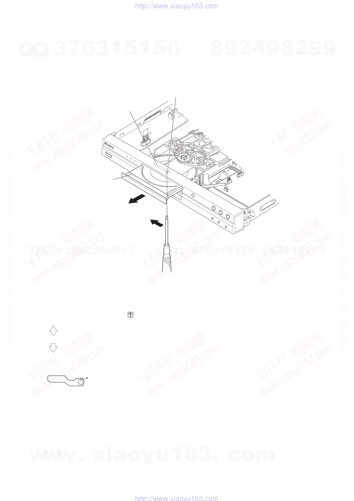
The lever of a zipper cam
B
A
Hold
Tray
Fig. 1.
SERVICE NOTE
1. DISC REMOVAL PROCEDURE (at POWER OFF)
1) Open dust cover to access to a hole insert a tapering driver into the aperture of the unit bottom, and move the lever of chuck can in the
direction of the arrow A. (See Fig. 1)
2) Draw out the tray in the direction of the arrow B, and remove a disc. (See Fig. 1)
2. PWB caution for B3834, IF-115 and PL-035 boards
Please ignore screw mark on A side, . Refer B side indication.
AV
: screw mount for NS775V
QS
: screw mount for NS955V/NS975V
For PL-035 board,
At this position, screw must mount for all model.
(NS775V, NS955V and NS975V)
J
w
w
w
.
x
i
a
o
y
u
1
6
3
.
c
o
m
Q
Q
3
7
6
3
1
5
1
5
0
9
9
2
8
9
4
2
9
8
T
E
L
1
3
9
4
2
2
9
6
5
1
3
9
9
2
8
9
4
2
9
8
0
5
1
5
1
3
6
7
3
Q
Q
TEL 13942296513 QQ 376315150 892498299
TEL 13942296513 QQ 376315150 892498299
http://www.xiaoyu163.com
http://www.xiaoyu163.com