HCD-SHAKE99/HCDSHAKE100
21
Ver. 1.1
SECTION 5
TROUBLESHOOTING
Switching Regulator Diagnosis Flow
The Output from Switching regulator is checked.
Is following power voltage up to standard?
Standby Demo mode Power On
CN201 pin1
CN401 pin2-4
AC IN
Yes
No
Yes
END
No
Check whether the state of the Cable and Outlet are normal.
If there are no problems, check circumference circuit for
Main on/Sub on Output of the Motherboard mount side.
Replaces Switching regulator if it is not up to standard.
The Power Control signal to Switching regulator is checked.
Is following power voltage OK?
Main on/Sub on Standby Demo mode Power On
CN 201 :pin6 Low (0V) Hi (3.3V) Hi (3.3V)
13V±0.5V
13V±0.5V
0V -62.5V±5%
pin5 0V -23V±5%
pin7 0V +23V±5%
pin8-10 0V +62.5V±5%
pin1 0V -48V±10%
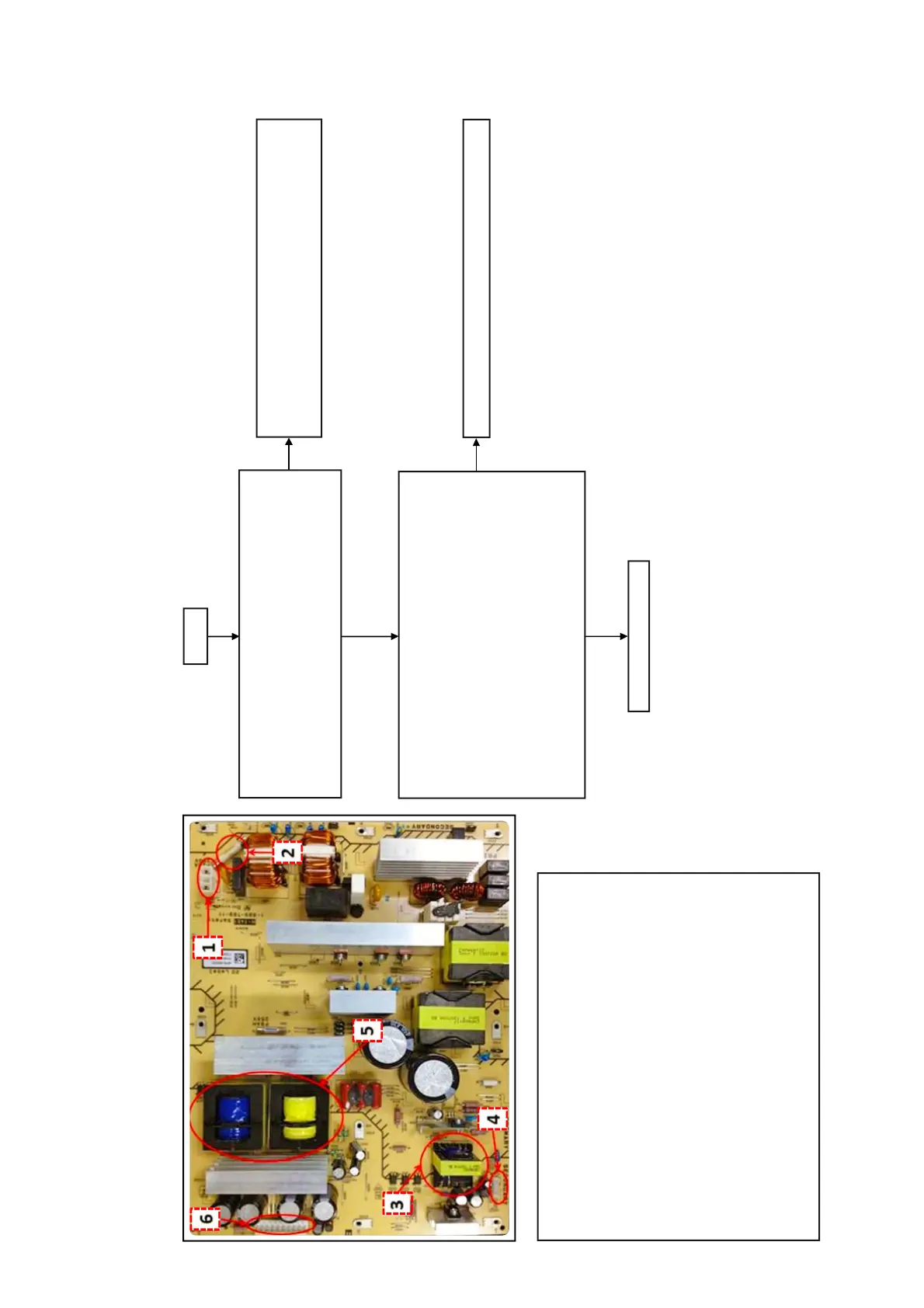
(1) AC input
(2) Fuse
(3) Sub Power transformer
(4) CN 201 Connector
pin1-2: 13V
pin3-4: GND
pin5: AC-DET
pin6: MAIN-ON
(5) MAIN Power transformer
(6) CN 401 Connector
pin1: V3- (DC-48V)
pin2-4: V1- (DC-62.5V)
pin5: V2- (DC-23V)
pin6: GND
pin7: V2+ (DC+23V)
pin8-10: V1+ (DC+62.5V)