1-2
SSC-DC593/DC593P/DC598P (E)
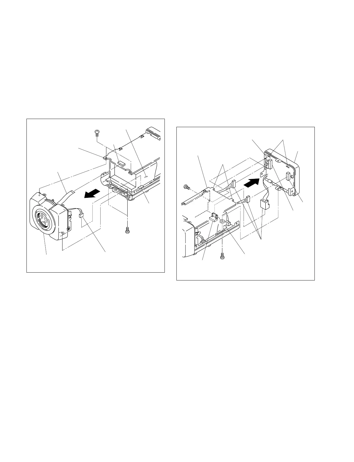
B 2x4
B 2x4
PR-269 board
Front assembly
CN201
CN3
Flexible flat cable
Harness
DC power
(The illustration indicates SSC-DC593.)
1-2-2. Front Assembly
1. Remove the upper case. (Refer to Section 1-2-1)
2. Remove the four screws, then remove the front
assembly in the direction indicated by the arrow.
3. Disconnect one flexible flat cable from the connector
(CN201) on the PR-269 board.
4. Disconnect one harness from the connector (CN3) on
the AC/DC power supply.
5. Attach the front assembly in the reverse order of steps
1 to 4.
PR-269 board
B 2x3
B 2x4
Projections
Holes
CN602
CN601
CN1
Harnesses
Rear
assembly
CT-221 board
AC/DC power supply
(The illustration indicates SSC-DC593.)
1-2-3. Rear Assembly
For SSC-DC593/DC593P
1. Remove the upper case. (Refer to Section 1-2-1)
2. Remove one screw (B 2x3) and one screw (B 2x4),
then remove the rear assembly in the direction
indicated by the arrow.
3. Disconnect the three harnesses from the connector
(CN1) on the AC/DC power supply and the connectors
(CN601 and CN602) on the CT-221 board.
4. Attach the rear assembly in the reverse order of steps 1
to 3.
n
When attaching the rear assembly, align the two
projections of the PR-269 board with the two holes of the
CT-221 board and attach it securely.
 Loading...