3-5
SSC-DC593/DC593P/DC598P (E)
3-3-3. 57 MHz Adjustment
1. Press the step forward button of the commander one
time. Then, “22” appears on the mode display.
2. Press the data change button so that the measuring
frequency is within the specification.
Subject: Not required
Measuring point: PR-269 board, CL201
Measuring equipment: Frequency counter
Mode display: 22
Specification: 57.272720 ±0.000800 MHz
(SSC-DC593)
56.750000 ±0.0000800 MHz
(SSC-DC593P/DC598P)
3-3-4. VCO Adjustment
1. Press the step forward button of the commander one
time. Then, “23” appears on the mode display.
2. Press the data change button so that the measuring
voltage is within the specification.
Subject: Not required
Measuring point: Adjustment Commander relay
tool board, TP6 (VCO CONT)
Measuring equipment: Digital voltmeter
Mode display: 23
Specification: 1.9 ±0.10 V
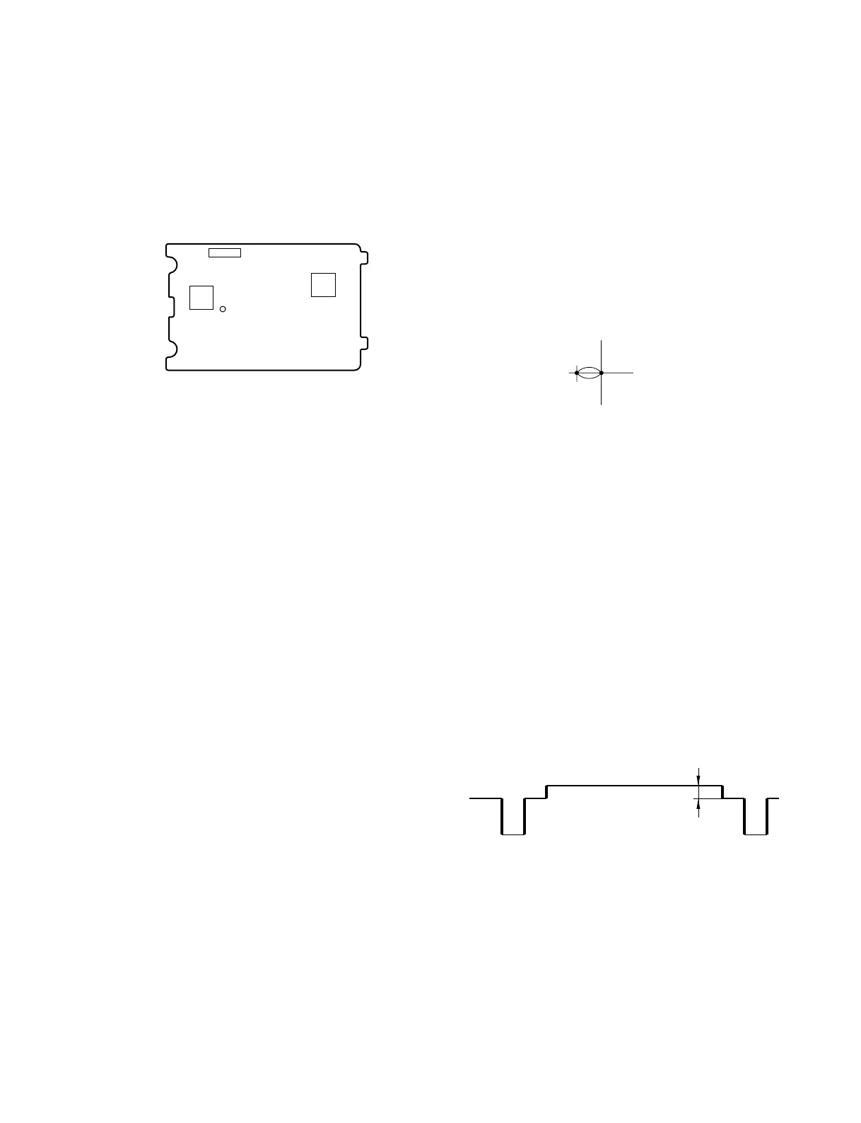
PR-269 board (Side A)
CL201
IC304
CN202
IC202
3-3-5. Burst Level Adjustment
1. Press the step forward button of the commander one
time. Then, “1D” appears on the mode display.
2. Press the data change button to meet the specification
on the vector.
Subject: Not required
Measuring point: Vectorscope
Mode display: 1D
Specification: Shall match with 75% mark.
3-3-6. SET UP Adjustment
1. Press the step forward button of the commander one
time. Then, “14” appears on the mode display.
2. Press the data change button so that the measuring
voltage is within the specification.
Subject: Not required
Measuring point: SET UP level of VIDEO OUT
Measuring equipment: Waveform monitor
Mode display: 14
Specification: 5 ±3 IRE
(SSC-DC593)
20 ±15 mV
(SSC-DC593P/DC598P)
Lens aperture: Close
75%
Center
 Loading...