1-4
SSC-DC593/DC593P/DC598P (E)
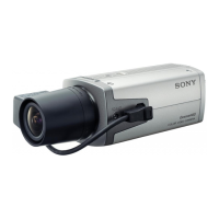
B 2x3
FC-92 board
Holes
CN701
CN702
Flexible flat cable
Harness
Projections
AC/DC power
supply
(The illustration indicates SSC-DC593.)
1-3-2. FC-92 Board
1. Remove the upper case. (Refer to Section 1-2-1)
2. Remove the PR-269 board. (Refer to Section 1-3-1)
3. Remove the two screws, then remove the FC-92 board
in the direction indicated by the arrow.
4. Disconnect one harness from the connector (CN701)
and one flexible flat cable from the connector (CN702)
on the FC-92 board.
5. Install the FC-92 board in the reverse order of steps 1
to 4.
n
When installing the FC-92 board, align the two projections
of the FC-92 board with the two holes of the AC/DC
power supply and attach it securely.
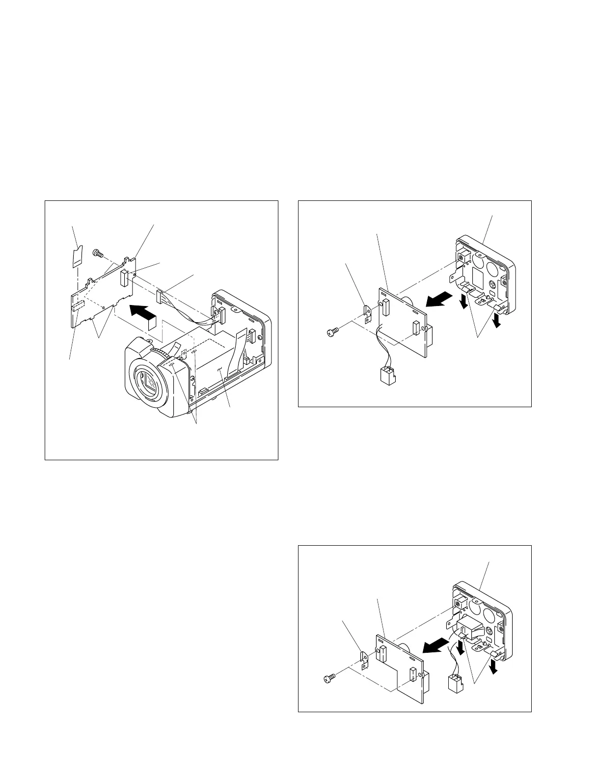
A
A
B
CT-221 board
Hooks
Rear assembly
Supporting
plate
BTP 2.6x6
(The illustration indicates SSC-DC593.)
1-3-3. CT-221 Board
For SSC-DC593/DC593P
1. Remove the upper case. (Refer to Section 1-2-1)
2. Remove the rear assembly. (Refer to Section 1-2-3)
3. Remove the two screws, then remove the supporting plate.
4.
Expand the two hooks of the rear assembly in the
direction indicated by the arrow A, then remove the
CT-221 board in the direction indicated by the arrow B.
5. Install the CT-221 board in the reverse order of steps 1 to 4.
For SSC-DC598P
1. Remove the upper case. (Refer to Section 1-2-1)
2. Remove the rear assembly. (Refer to Section 1-2-3)
3. Remove the two screws, then remove the supporting plate.
4. Expand the two hooks of the rear assembly in the
direction indicated by the arrow A, then remove the CT-
221 board in the direction indicated by the arrow B.
5. Install the CT-221 board in the reverse order of steps 1 to 4.
A
A
B
CT-221 Board
Hooks
Rear assembly
Supporting
plate
BTP 2.6x6
 Loading...