1-5
SSC-DC593/DC593P/DC598P (E)
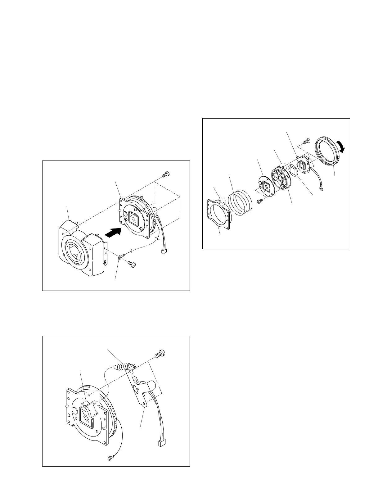
B 2x4
B 2x4
Ring base
Front assembly
Harness (with round terminal)
Motor assembly
Helical extension spring
Shutter lever
BTP 2x5
7. Rotate the ring in the direction indicated by the arrow,
then remove the helical compression spring and optical
shutter block from the ring base.
8. Remove the three screws from the shutter block
assembly, then remove the filter lid assembly.
9. Remove the three screws from the shutter block
assembly, then remove the blind cover and CCD
assembly.
10. Attach the CCD assembly, optical shutter block and
motor assembly in the reverse order of steps 1 to 9.
n
When attaching the optical shutter block, align the
projection of the optical shutter block with the ring base
notch and attach it.
1-4. Motor Assembly/Optical Shutter
Block/Installation and Removal of
CCD Assembly
n
When removing the ring, be careful with the helical
compression spring because it may pop up.
1. Remove the upper case. (Refer to Section 1-2-1)
2. Remove the front assembly. (Refer to Section 1-2-2)
3. Remove one screw, then disconnect the harness (with
round terminal).
4. Remove the four screws, then remove the ring base.
5. Remove the helical extension spring from the shutter
lever.
6. Remove the two screws, then remove the motor
assembly.
Ring
CCD assembly
Blindfold cover
Optical shutter
block
Helical compression
spring
Ring base
Notch
BTP
2x5
Projection
Filter lid assembly
BTP
2x5
 Loading...