14
STR-DA2000ES/DB2000
SECTION 5
ELECTRICAL ADJUSTMENTS
DC OFFSET ADJUSTMENT
Condition:
function: MULTI CH 2
input signal: no signal (no load)
volume: 0 dB
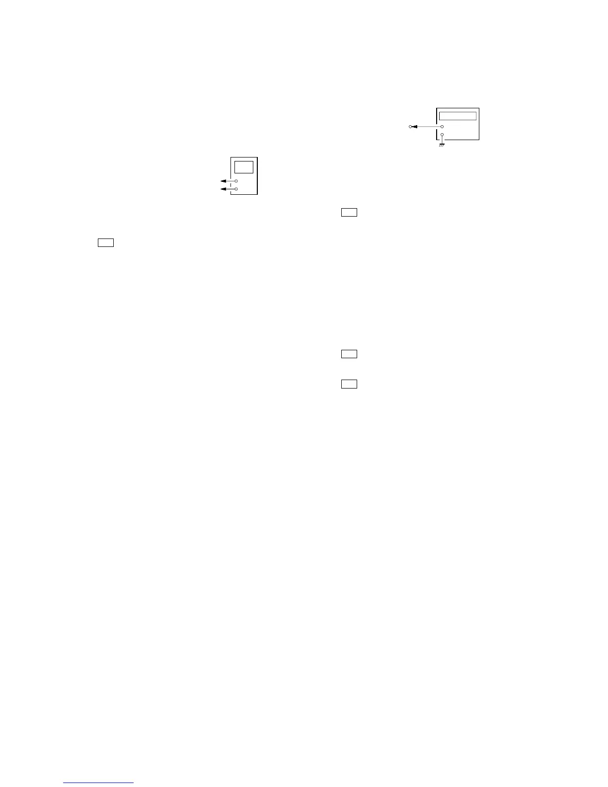
Connection
Procedure:
1. Connect a digital voltmeter to the TM1710 (TM1730, 1740,
1750, 1760, 1770) on the D. AMP board.
2. Press the I/1 button to turn on the main power.
3. Adjust the RV111 (141, 161, 181, 211, 241, 281) on the MULTI-
VIDEO board so that the digital voltmeter reading is ±20 mV.
Adjustment and Connection Location: see page 15
+
–
digital voltmete
D. AMP board
TM1710 (TM1730, 1740, 1750, 1760, 1770)
3
pin
TM1710 (TM1730, 1740, 1750, 1760, 1770)
#
pin
OSD ADJUSTMENT
Connection
Procedure:
1. Short the CN1241 pin 4 on the MULTI-VIDEO board to the
GND.
2. Connect a frequency counter to the CN1241 pin 2 on the
MULTI-VIDEO board.
3. Press the I/1 button to turn on the main power.
4. Press the [MAIN MENU] button to display “CUSTOMIZE ”.
5. Turn the [MENU] jog clockwise to display “OSD COLOR
[NTSC]”. If “OSD COLOR [PAL]” is displayed, turn the [--/+]
jog counterclockwise.
6. Turn the [MENU] jog clockwise to display “OSD H.POSI [X]”.
7. Adjust the CT1261 (STR-DA2000ES) or CT1271 (STR-
DB2000) so that the frequency counter reading is 3.57954 MHz.
8. Turn the [MENU] jog counterclockwise to display “OSD
COLOR [NTSC]”.
9. Turn the [--/+] jog clockwise to display “OSD COLOR [PAL]”.
10. Turn the [MENU] jog clockwise to display “OSD H.POSI [X]”.
11. Adjust the CT1272 so that the frequency counter reading is
4.43361 MHz.
12. Press the I/1 button to turn off the main power.
13. Connect a frequency counter to the CN1241 pin 1 on the
MULTI-VIDEO board.
14. Press the I/1 button to turn on the main power.
15. Press the
[MAIN MENU] button to display “CUSTOMIZE”.
16. Turn the [MENU] jog clockwise to display “OSD V.POSI [X]”.
17. Adjust the CT1241 so that the frequency counter reading is 7.20
MHz.
Note: The steps 5 and 8 to 11 should be performed to STR-DB2000.
Adjustment and Connection Location: see page 15