6
STR-DA2000ES/DB2000
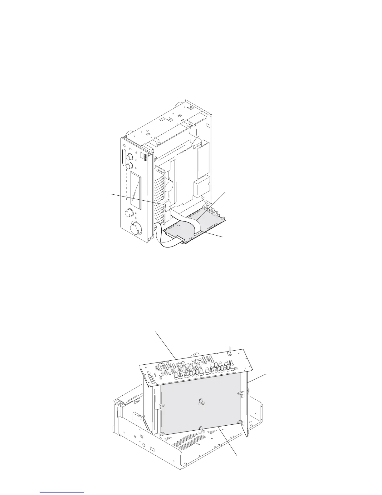
D. AMP BOARD SERVICE POSITION
1
Remove the case (Refer to page 10).
2
Remove the switching regulator (Refer to page 10)
3
Remove the main block (Refer to page 10).
4
Set the switching regulator to the main block.
5
Set the main block at the shown in the figure.
D. AMP board
(bottom view)
main bloc
rear panel
D. AMP board
(CN1901)
digital board
(CN2006)
Connect jig
(extension cable J-2501-220-A
to the digital board (CN2006)
and D. AMP board (CN1901)
In checking the digital board, prepare jig (extension cable J-2501-220-A: 1.25 mm Pitch,
27 cores, Length 300 mm).
DIGITAL BOARD SERVICE POSITION