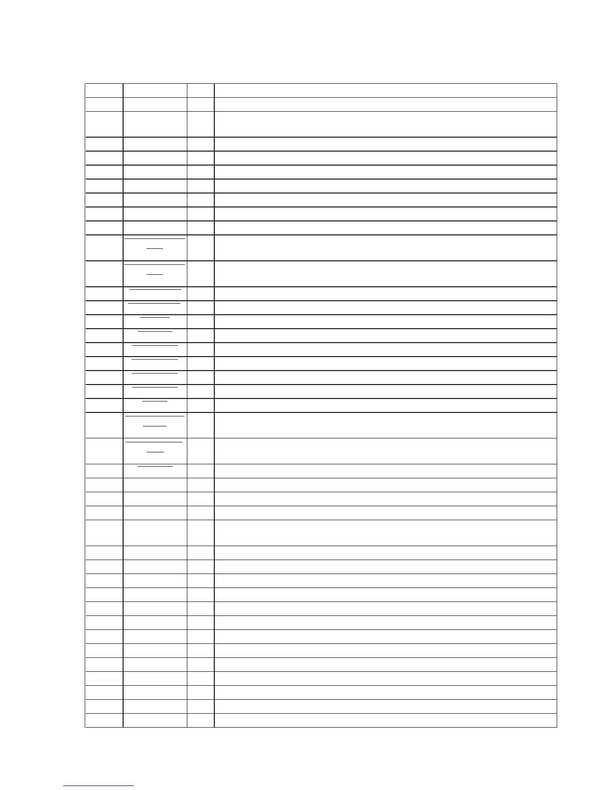
65
STR-DB795
DIGITAL BOARD IC1703 MB91154PFV-G-121-BNDE1 (SYSTEM CONTROLLER)
Pin No.
Pin Name
I/O Description
1
PW RY
O
Relay drive signal output terminal (for main power) "H": relay on
2
H/P RY
O
Relay drive signal output terminal (for headphone) "H": relay on
3
SP.A.RY
O
Relay drive signal output terminal (for front A speaker) "H": relay on
4
SP B RY
O
Relay drive signal output terminal (for front B speaker) "H": relay on
5
SURR.RY
O
Relay drive signal output terminal (for surround speaker) "H": relay on
6
CTR/SW RY
O
Relay drive signal output terminal (for sub woofer) "H": relay on
7
SB.RY
O
Relay drive signal output terminal (for center/surround back speaker) "H": relay on
8
SUB T
O
Relay drive signal output terminal (for standby power) "H": relay on
9
VSS
-
Ground terminal
10
FUNCTION.JOG
(2B)
I
Jog dial pulse input from the rotary encoder (B phase input) (for INPUT SELECTOR)
11
FUNCTION.JOG
(2A)
I
Jog dial pulse input from the rotary encoder (A phase input) (for INPUT SELECTOR)
12 VOL.JOG (1B)
I
Jog dial pulse input from the rotary encoder (B phase input) (for MASTER VOLUME)
13 VOL.JOG (1A)
I
Jog dial pulse input from the rotary encoder (A phase input) (for MASTER VOLUME)
14 FL CLK
O
Serial data transfer clock signal output to the fluorescent indicator tube driver
15 FL DATA
O
Serial data output to the fluorescent indicator tube driver
16
+/-.JOG (4B)
I
Jog dial pulse input from the rotary encoder (B phase input) (for MENU)
17
+/-.JOG (4A)
I
Jog dial pulse input from the rotary encoder (A phase input) (for MENU)
18
+/-.JOG (3B)
I
Jog dial pulse input from the rotary encoder (B phase input) (for -/+)
19
+/-.JOG (3A)
I
Jog dial pulse input from the rotary encoder (A phase input) (for -/+)
20
SP SW
I
Speaker switch input terminal "L": speaker on
21
VOL IC/TUNER
DATA
O
Serial data output to the tuner unit, audio selector, video selector and electrical volume
22
VOL IC/TUNER
CLK
O
Serial data transfer clock signal output to the tuner unit, audio selector, video selector and
electrical volume
23 VOL LAT
O
Serial data latch pulse signal output to the audio selector, video selector and electrical volume
24, 25 NC
-
Not used
26
VSS
-
Ground terminal
27
VCC
-
Power supply terminal (+3.3V)
28
RESET UP
CONVERT
-
Not used
29 to 32 NC
-
Not used
33 TP1
-
Not used
34 to 37 NC
O
Not used
38 to 40 TP4 to TP6
O
Not used
41 HP DETECT
I
Headphone detection signal input terminal "H": headphone is connected
42 D.POWER
O
Digital section power on/off control signal output terminal "H": power on
43 V.POWER
O
Video section power on/off control signal output terminal "H": power on
44 VSS
-
Ground terminal
45, 46 NC
-
Not used
47
RDS.DATA
I
RDS serial data input from the tuner unit (AEP and UK models only)
48 TUNER ST
I
FM stereo detection signal input from the tuner unit
49
TUNER TUNED
I
Tuned detection signal input from the tuner unit
50
TUNER MUTE
O
Muting request control signal output to the tuner unit