17
KV-27FA310/27FS120/29FA310/29FS120
KV-27FA310/27FS120/29FA310/29FS120
Hold-Down Readjustment
If the setting indicated in Step 2 of Hold-Down Operation Confi rmation
cannot be met, readjustment should be performed by altering the
resistance value of R564 component marked with
X
.
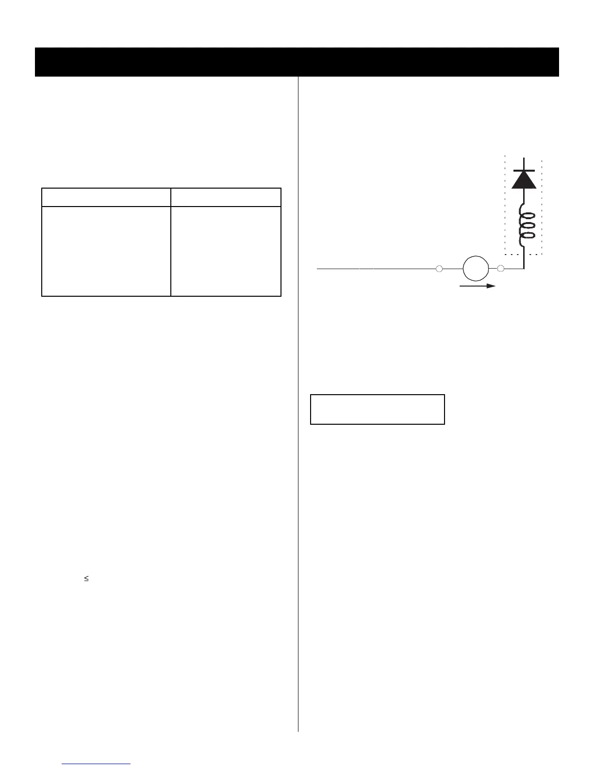
+
IABL
ABL
T585
FBT
range
-
ammeter
3.0 mA DC
A
3-2. B+ VOLTAGE CONFIRMATION AND
ADJUSTMENT
Note: The following adjustments should always be performed when
replacing the following components, which are marked with
Y
on the
schematic diagram on the A Board:
A BOARD:
Y
IC604, PH602
1. Using a Variac, apply AC input voltage: 130 + 2.0 / - 0.0 VAC.
2. Input a DOT pattern at Q.C.
3. Set the PICTURE and the BRIGHTNESS controls to minimum.
4. Confi rm the voltage of A Board between TP-23 & Ground is =135.6
± 1VDC.
5. If step 4 is not satisfi ed, replace the components listed above, then
repeat steps 1 throught 3.
SECTION 3: SAFETY RELATED ADJUSTMENTS
3-1. X R564 CONFIRMATION METHOD
(HV HOLD-DOWN CONFIRMATION) AND
READJUSTMENTS
The following adjustments should always be performed when replacing
the following components which are marked with
Y
on the schematic
diagram:
DY, T585, CRT, IC001, IC561,
IC600, IC604, C506, C507,
C508, C510, C511, C513,
C514, L588, D566, D567,
D568, PH602, R526, R564,
R565, R566, R851, T510,
T511……....A Board
HV HOLD-DOWN
R564
Part Replaced (Y) Adjustment (X)
Preparation Before Confi rmation
1. Using a Variac, apply AC input voltage: 120 ± 2 VAC.
2. Turn the POWER switch ON.
3. Input a white signal and set the PICTURE and BRIGHTNESS
controls to maximum.
4. Confi rm that the voltage between C566 (+) or TP30 and ground is
more than 99VDC.
Hold-Down Operation Confi rmation
1. Connect the current meter between Pin 11 of the FBT (T585) and the
PWB land where Pin 11 would normally attach (See Figure 1 on the
next page).
2. Input a dot signal and adjust the ABL current to follow with the
PICTURE and BRIGHTNESS control: IABL = 140 ± 100µA.
3. Confi rm the voltage of A Board TP-23 is 135.6 ± 1.0VDC.
4. Connect the digital voltmeter and the DC power supply via Diode
1SS119 to C566 (+) and ground (See Figure 1 on next page).
5. Increase the DC power voltage gradually until the picture blanks out.
6. Turn DC power source off immediately.
7. Read the digital voltmeter indication
(Standard
114.6 +OVDC/-0.3DC).
8. Input 100 IRE White Signal and adjust the ABL current to follow with
the PICTURE and BRIGHTNESS control: IABL = 1820µA ± 200µA.
9. Repeat steps 4 through 7.