32
KV-27FA310/27FS120/29FA310/29FS120
KV-27FA310/27FS120/29FA310/29FS120
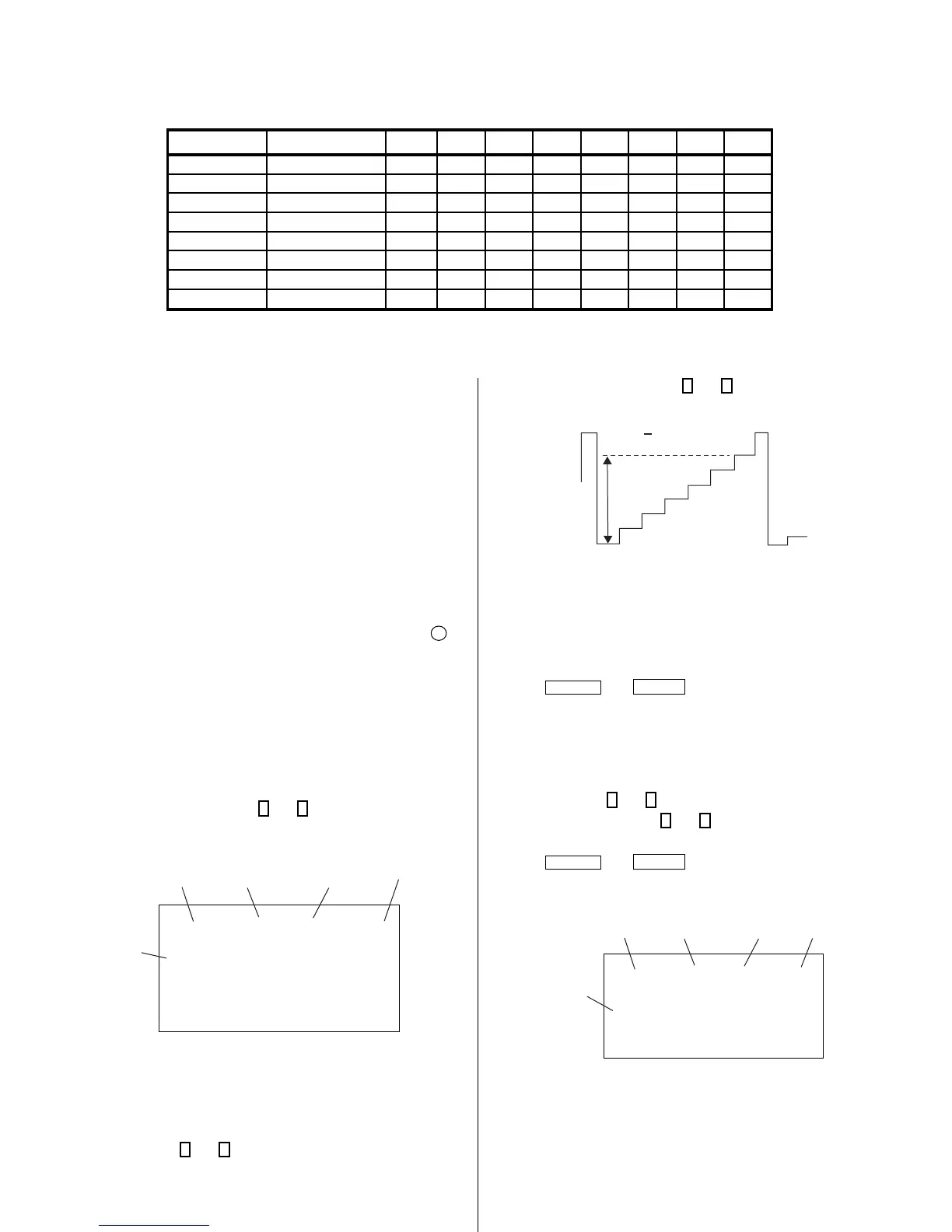
4-5. ID MAP TABLE
Model Destination ID-O ID-1 ID-2 ID-3 ID-4 ID-5 ID-6 ID-7
KV-27FA310 US 81 31 17 130 32 24 48 69
KV-27FA310 CND 81 31 17 130 32 24 48 69
KV-27FS120 US 89 31 17 34 0 24 0 5
KV-27FS120 CND 89 31 17 50 0 24 0 5
KV-29FS120
L NORTH
81 31 17 130 32 24 48 69
KV-29FS120
L SOUTH
81 31 17 130 32 24 48 69
KV-29FA310
L NORTH
81 31 113 130 32 24 48 69
KV-29FA310
L SOUTH
81 31 113 130 32 24 48 69
7. Adjust the value of SCON with
3
and
6
for 87 ± 2Vpp.
87 + 2Vpp
8. Reset GON and BON values to “1”.
R ON: ON (1)
G ON: ON (1)
B ON: ON (1)
9. Press
MUTING
then
ENTER
to save into the memory.
Display Position Adjustment (DISP)
1. Input a color-bar signal.
2. Set to Service Adjustment Mode.
3. Select DISP with
1
and
4
.
4. Adjust values of DISP with
3
and
6
to adjust characters to the
center.
5. Press
MUTING
then
ENTER
to save into the memory.
6. Check to see if the text is displayed on the screen.
service micro disp 48
ntsc
vchp
Category
Display
Item
Mode
Item
Data
Signal
Type
00000000 00000000
4-6. A BOARD ADJUSTMENTS
H. Frequency (Free Run) Check
1. Input a TV mode (RF) with no signal.
2. Connect a frequency counter to base of Q502
(TP-25 H. DRIVE) on the A Board.
3. Check H. Frequency for 15735 ± 200 Hz.
V. Frequency (Free Run) Check
1. Select video 1 with no signal input.
2. Set the conditions for a standard setting.
3. Connect the frequency counter to TP-27 (V OUT) or CN515 pin
6
(V DY+) and ground on the A Board .
4. Check that V. Frequency shows 60 ± 4 Hz.
Drive (SCON)
1. Input a color-bar signal and set the level to 75%.
2. Set in Pro mode + PICTURE MAX.
3. Activate the Service Adjustment Mode.
4. Set GON and BON items. Using
3
and
6
set each to the following
values. Leave RON set to “1”.
service video rdrv
ntsc
vchp
Category
Display
Item
Mode
Item
Data
Signal
Type
00000000 00000000
26
R ON: ON (1)
G ON: OFF (0)
B ON: OFF (0)
5. Connect an oscilloscope probe to CW Board, JW2704 (KR).
6. Select SCON with
1
and
4
.