Home
Sony
Monitor
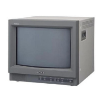
Trinitron PVM-14L2
Sony Trinitron PVM-14L2 Service Manual
5
of 1
of 1 rating
174 pages
Give review
Manual
Specs
To Next Page
To Next Page
To Previous Page
To Previous Page
Loading...
8-4
PVM-14L2/20L2
8-4
G (2/2), J, DY
G (2/2), J, DY
LIVE
1
G (2/2)
NEUTRAL
3
AC IN
CN601
CN603
THP601
LINE
FILTER
CN602
(2/2)
RY602
LATCH
Q604,605
DEGAUS
DRIVE
Q601,602
RY601
RELAY
DRIVE
Q603
1
3
5
6
9
VCC
DRA IN
1
AC SENSE
3
CATHODE
10
5
L SENSE
IC601
POWER FACTOR CONT
T602
PFT
Q614
ON/OFF
13
11
VCC
9
OUT
7
OCL
14
VREF
IC602
PWM POWER CONT
7
9
12
13
14
T602
SRT
17
18
4
3
1
2
PH602
PROT
Q607
4
3
1
2
PH601
D603
AC RECT
1
DGC
+12V
REG
15
16
IC604
+5V
REG
IC606
-5V
REG
IC607
2
1
O.C.P
Q608
LATCH
Q609,610
+15V
+12V
+180V
-5V
3
7
8
1
G2
H2
+180V
H1
CN607
D608
+B
1
5
11
8
T501
DFT
1
3
2
HV
PROT
6
2
1
HV
14
13
FV
16
7
15
T502 FBT
5
IC503
IC502(1/2)
2
3
1
D516
HV PROT
11
FV
17
18
C BOARD
PICTURE TUBE
PROT
+12V
+B
HV
DF AMP
Q503-505
BUFF
Q501,502
1
3
2
IK
PROT
IC505
IC502(2/2)
5
6
7
D514
IK PROT
+12V
7
5
AC L IN
AC IN
1
3
CN011
(1/2)
7
5
AC L OUT
AC OUT
1
3
CN011
(2/2)
CN602
(1/2)
J
3
DGC
12
OVL
Q606
6
4
10
11
RECT
D613
RECT
D619
RECT
D614
RECT
D616
RECT
D628
RECT
D618
RECT
D617
RECT
D615
+5V
REG
IC605
OP +5V
OP +6V
+5V
OP -8V
-15V
LATCH
Q611,612
PROT
Q613
PROT
1
2
3
IC603
HEATER
REG
Q619
+180V
8
4
12
1
AFC (HP)
CN1502
H SYNC
V SYNC
SDA
2
SCL
9
UNLOCK
14
V BLK (W)
H IN
26
IC1551
H/V JUNGLE
13
HDF
500K
29
SDA
3
SCL
4
HP
14
X1550
500K
17
H OUT
9
EW
8
V OUT
H DRIVE
Q1505
H OUT
Q1506
-VIN
1
IC1501
V OUT
+VIN
7
5
OUT
1
2
3
4
L1505
L1504
HLC
T1501
HLT
1
H DY+
CN1506
2
H DY+
3
H DY-
4
H DY-
5
V DY-
6
V DY+
DY
1
FB GEN
FBT/REG
DYNAMIC FOCUS
+5V
REG
+12V
+5V
IC1502
6
ABL
1
3
V IN
28
IC1552
H BUFF
Q1550
Q1552
V BUFF
Q1551
31
IC1550
PIN AMP
Q1553
4
6
1
3
T1502
HDT
+B
DUMPER
D1508-1510
3
4
1
4
L1502
V PROT
Q1501.1502
14L2 ONLY
+B
H CENT
RV1501
HP BUFF
Q1508
VP BUFF
Q1509
B
B BOARD (3/3)
CN321(2/2)
A
B BOARD (2/3)
CN321(1/2)
V
BUFF
20L2
ONLY
PIN OUT
Q512
Q513
H FOCUS
+B
ABL
13
V CENT
11
VP
PROT
()
CN608
1
DGC
2
DGC
CN510(2/2)
5
DEGAUSS
S001
C
BB BOARD(3/3)
CN106(2/2)
BUFF
Q617,618
D630
2
FB
Q615,616
D612
D
C BOARD
CN702,704
14L2/14L2A
D
C BOARD
CN702
20L2/20L2A
D515
20L2 ONLY
D501
ABL
H FOCUS
T601
137
139
Table of Contents
Default Chapter
3
Table of Contents
3
1 Service Informations
7
Board Locations (14 Inch)
7
Disassembly (14 Inch)
8
Top Cover and Rear Cover Removal (14 Inch)
8
B and B1 Boards Removal (14 Inch)
9
Q Board Removal (14 Inch)
10
G and Q Block Assy Removal (14 Inch)
11
G Board Removal (14 Inch)
11
C Board Removal (14 Inch)
12
Picture Tube and Bezel Assy Removal (14 Inch)
12
H, J and X Boards Removal (14 Inch)
13
Removal of Anode Cap (14 Inch)
13
Board Locations (20 Inch)
14
Disassembly (20 Inch)
15
Top Cover and Rear Cover Removal (20 Inch)
15
B and B1 Boards Removal (20 Inch)
16
Q Board Removal (20 Inch)
17
G and Q Block Assy Removal (20 Inch)
18
G Board Removal (20 Inch)
18
J and H Boards Removal (20 Inch)
19
Picture Tube, Bezel Assy and X Board Removal (20 Inch)
20
Removal of Anode Cap (20 Inch)
21
2 Set-Up Adjustment
23
Equipment Required
23
Service Mode
23
Operating the Service Mode
23
Preparations (1)
23
Executing FACTORY LOAD
24
Executing FACTORY SAVE
24
Factory Set
24
Service Mode Screen Display
25
Writing Model Data
29
Picture Output
29
AC Input Voltage Setting
29
Preparation (2). Initialization
29
Free-Run Frequency Adjustment
30
Landing Adjustment
30
14 Inch
31
20 Inch
31
H Blanking Adjustment
32
Defection Adjustment
32
DY Inclination Distortion Check
32
Picture Size Specifications
33
H. Size
33
V. Size
33
Convergence Adjustment (1)
34
V-STAT Mg Knob
34
Deflection Yoke Neck Rotation Adjustment
35
Convergence Adjustment (2)
35
White Balance Adjustment (15K)
36
Group of Models Inch 14
36
G2 Adjustment
36
Conditions
36
White Balance Adjustment (33 K)
37
SUB BRIGHT, SUB CONTRAST Adjustment (15 K)
37
White Balance Interference Correction Adjustment
38
NTSC Composite Adjustment
38
PAL Composite Adjustment
38
COMPONENT Adjustment
38
SUB BRIGHT, SUB CONTRAST Adjustment (33 K)
38
SDI Adjustment
38
Focus Adjustment
39
BLK Adjustment
39
FBT Focus VR Controls (20 Inch)
39
3 Safety Related Adjustment
41
+B Voltage Check
41
G Board (HV Protector Circuit)
41
High Tension Regulator Confirmation
42
HV Protector Circuit Confirmation
42
4 Electrical Adjustments
43
Equipment Required
43
B Board Adjustments
44
Preparation of Signals
44
Test Point
44
NTSC SETUP 0 Mode Adjustment
45
Connection Diagram
45
Y/C Input
45
Composite Input
46
NTSC SETUP 7.5 Mode Adjustment
46
Y/C Input
46
PAL Mode Adjustment
47
Composite Input
47
Y/C Input
47
Y PBPR BETACAM SETUP 0 Signal
48
Y PBPR SMPTE (601) Signal
48
Y PBPR BETACAM SETUP 7.5 Signal
49
5 Theory of Operation
51
B Board
51
Input Section - Decoder Section
51
Video Signal and Y/C Signal
51
CXA1739S Peripheral Circuit
52
ABL Circuit
52
Blanking Pulse Shaping
52
BLUE ONLY Circuit
52
Defection and High Voltage Circuit
53
Sync Signal Processing Circuit
53
Horizontal Output Circuit
53
Vertical Output Circuit
53
Power Supply Circuit
54
Power Factor Improvement Block
54
Power Regulator for the Main Power Supply
54
Overvoltage Protection and Over-Current Protection Circuits
55
6 Semiconductors
57
Transistor, Diode
58
7 Spare Parts
61
Notes on Repair Parts
61
Safety Related Components Warning
61
Standardization of Parts
61
Exploded Views
62
G, Q Board Section (14 Inch)
64
Chassis and Bezel Assy Section (14 Inch)
66
Picture Tube Section (14 Inch)
68
Top Cover Section (20 Inch)
70
G, Q Boards Section (20 Inch)
72
Chassis and Bezel Assy Section (20 Inch)
74
Picture Tube Section (20 Inch)
76
Electrical Parts List
78
8 Block Diagrams
135
B (1/3), B1, Q (1/2), G (1/2)
135
B (2/3), C, H (1/2)
136
G (2/2), J, Dy
138
9 Diagrams
139
Resistor
139
Capacitor
139
Schematic Diagrams and Board Layouts
140
C (Pvm-14L2)
152
C (Pvm-20L2)
154
C (Pvm-14L2)
157
Leakage Test
173
Safety Check-Out
173
Using an AC Voltmeter to Check AC Leakage
173
C (Pvm-20L2)
174
Other manuals for Sony Trinitron PVM-14L2
Instructions For Use
112 pages
5
Based on 1 rating
Ask a question
Give review
Questions and Answers:
Need help?
Do you have a question about the Sony Trinitron PVM-14L2 and is the answer not in the manual?
Ask a question
Sony Trinitron PVM-14L2 Specifications
General
Screen Size
14 inches
Display Type
CRT
Aspect Ratio
4:3
Weight
15.4 kg
CRT Type
Trinitron
Input Connectors
S-Video
Audio Inputs
RCA
Related product manuals
Sony Trinitron PVM-14L5
80 pages
Sony TRINITRON PVM-14L1
76 pages
Sony Trinitron PVM-14L4
160 pages
Sony Trinitron PVM-14L3
160 pages
Sony Trinitron PVM-14L2MD
16 pages
Sony Trinitron PVM-14L1MDE
84 pages
Sony Trinitron PVM-14N5U
76 pages
Sony Trinitron PVM-14N1E
15 pages
Sony Trinitron PVM-14N6A
76 pages
Sony Trinitron PVM-1454QM
12 pages
Sony trinitron PVM-1450QM
113 pages
Sony Trinitron PVM-14M2MDE
111 pages