4-3
PVM-14L2/20L2
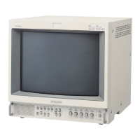
3. Connection diagram
CN701CN1502
CN102 CN231 CN230
CN104
CN103
CN605CN52CN51
HGC
B
Q
CN450
CN452
CN2710 CN2705
SG
(VG-854)
equivalent
SG
(TG-2000)
equivalent
Set
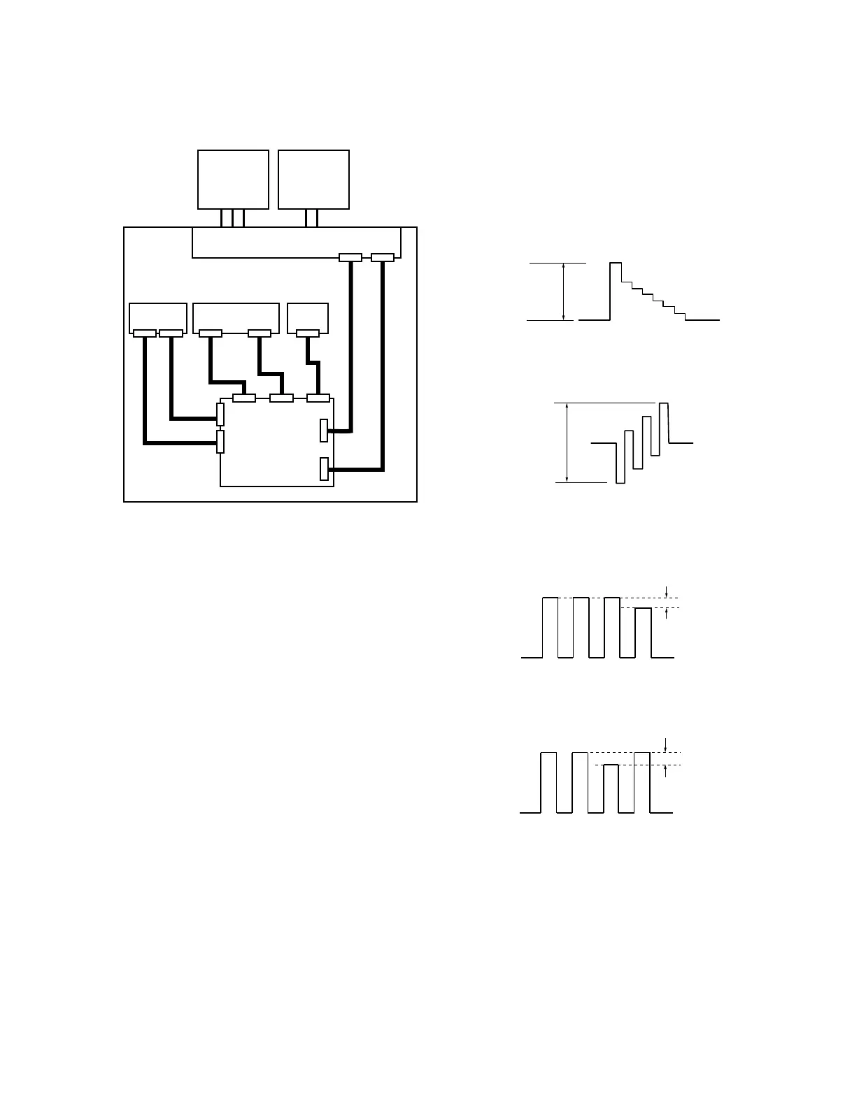
4-2-2. NTSC SETUP 0 Mode Adjustment
4-2-2-1. Y/C Input
1. Input the NTSC SETUP 0 100 % color bar signal to
the Y/C IN connector of INPUT A.
2. Adjust Y LEVEL (AZ_29) of the menu until the
waveform at TP106 meets the standard value.
Standard value : A = 620 ±10 mV
3. Adjust C LEVEL (AZ_35) of the menu until the
waveform at TP107 meets the standard value.
Standard value : B = 620 ±10 mV
4. Adjust SUB CHROMA (A0_75) of the menu until the
portions A and D of the waveform at TP350 (B board)
become flat.
5. Adjust SUB PHASE (A0_8B) of the menu until the
portions B and C of the waveform at TP350 become
flat.
A
B
10 mV less
ABCD
10 mV less
ABCD

 Loading...