4-5
PVM-14L2/20L2
4-2-4. PAL Mode Adjustment
4-2-4-1. Y/C Input
1. Input the PAL 100 % color bar signal to the Y/C IN
connector of INPUT A.
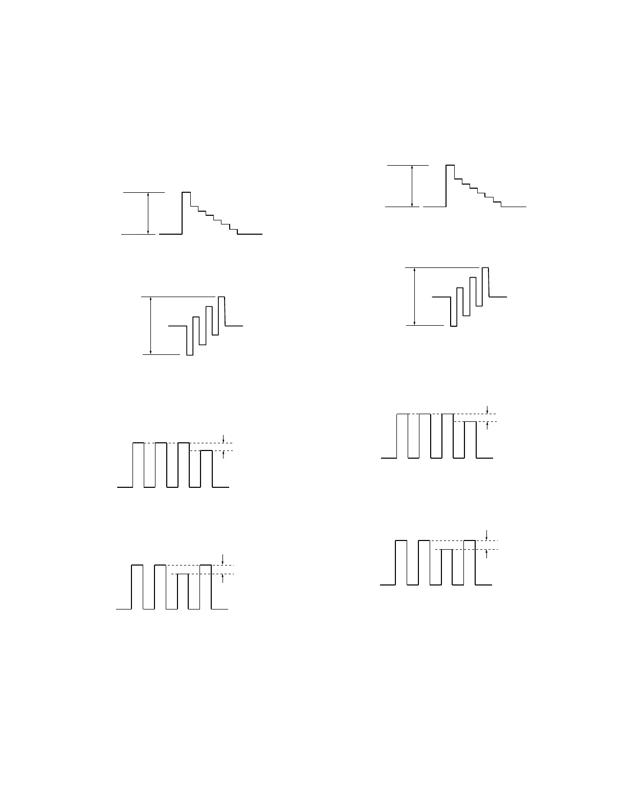
2. Adjust Y LEVEL (A2_2B) of the menu until the
waveform at TP106 meets the standard value.
Standard value : A = 620 ±10 mV
3. Adjust C LEVEL (A2_37) of the menu until the
waveform at TP107 meets the standard value.
Standard value : B = 620 ±10 mV
4. Adjust SUB CHROMA (A0_79) of the menu until the
portions A and D of the waveform at TP350 (B board)
become flat.
5. Adjust SUB PHASE (A0_90) of the menu until the
portions B and C of the waveform at TP350 become
flat.
A
B
10 mV less
ABCD
10 mV less
ABCD
4-2-4-2. Composite Input
1. Input the PAL 100 % color bar signal to the VIDEO
IN connector of INPUT A.
2. Adjust Y LEVEL (A2_25) of the menu until the
waveform at TP106 meets the standard value.
Standard value : A = 620 ±10 mV
3. Adjust C LEVEL (A2_31) of the menu until the
waveform at TP107 meets the standard value.
Standard value : B = 620 ±10 mV
4. Adjust SUB CHROMA (A0_78) of the menu until the
portions A and D of the waveform at TP350 (B board)
become flat.
5. Adjust SUB PHASE (A0_8F) of the menu until the
portions B and C of the waveform at TP350 become
flat.
A
B
10 mV less
ABCD
10 mV less
ABCD

 Loading...