1
VPL-CS7/ES2
Table of Contents
1. Service Overview
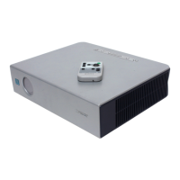
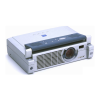
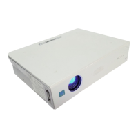
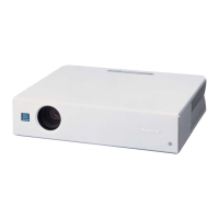
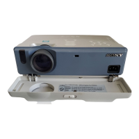
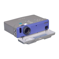
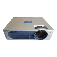
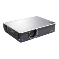
1-1. Appearance Figure ...................................................................................... 1-1
1-2. Board Locations ..........................................................................................1-1
1-3. Disassembly ................................................................................................1-2
1-3-1. Top Panel Assembly ..................................................................1-2
1-3-2. H Board ......................................................................................1-2
1-3-3. C Board ...................................................................................... 1-3
1-3-4. Lens Gear ...................................................................................1-4
1-3-5. Fan Holder..................................................................................1-4
1-3-6. D.C. Fan (60 mm) and D.C. Fan (70 mm) ................................1-5
1-3-7. Lamp House ............................................................................... 1-5
1-3-8. Optics Block Assembly ..............................................................1-6
1-3-9. Prism Block Assembly ...............................................................1-6
1-3-10. Incidence Polarizer (R), (G), (B)................................................1-7
1-3-11. Side Panel Assembly-1 ..............................................................1-8
1-3-12. Side Panel Assembly-2 ..............................................................1-9
1-3-13. G Board ....................................................................................1-10
1-3-14. Lamp Power Supply .................................................................1-10
1-3-15. D.C. Fan (Sirocco/For Lamp) ..................................................1-11
1-3-16. D.C. Fan (Sirocco) ...................................................................1-12
1-3-17. Adjuster Block Assembly ........................................................1-13
1-4. Note on Power Cord..................................................................................1-14
2. Electrical Adjustments
2-1. Preparation .................................................................................................. 2-1
2-1-1. Required Equipment...................................................................2-1
2-1-2. Opt Unit Adjustment ..................................................................2-1
2-1-3. How to Enter the Factory Mode .................................................2-2
2-2. V COM Adjustment ....................................................................................2-2
2-3. Initial Values of Adjustment Items ............................................................. 2-3
2-4. Service Know-How ...................................................................................2-13
2-4-1. When the Prism Block is Replaced ..........................................2-13
2-4-2. When the C Board is Replaced ................................................ 2-13
2-5. White Balance Adjustment .......................................................................2-14
2-5-1. HIGH Mode of INPUT-A ........................................................2-14
2-5-2. LOW Mode of INPUT-A .........................................................2-14
2-5-3. HIGH Mode of VIDEO............................................................2-14
2-5-4. LOW Mode of VIDEO.............................................................2-14
2-6. Memory Structure .....................................................................................2-15
3. Semiconductors