TU BOARD
EXT ANT
SWITCH BOARD
1
1-676-091
11
1-677-033-
(11)
11
04
MAIN BOARD
CNP306
MW/LW
ANTENNA
FM EXT
ANTENNA
FM ANTENNA
SELECTOR
FM TELESCOPIC
ANTENNA
S1
S1
J1-2 J1-1
EXT
TUNER
UNIT
ANT1
1
A
B
C
D
E
F
G
H
I
J
2345678
14
MAIN BOARD
CN302
TP(VT)
ZS-2000
– 31 – – 32 –
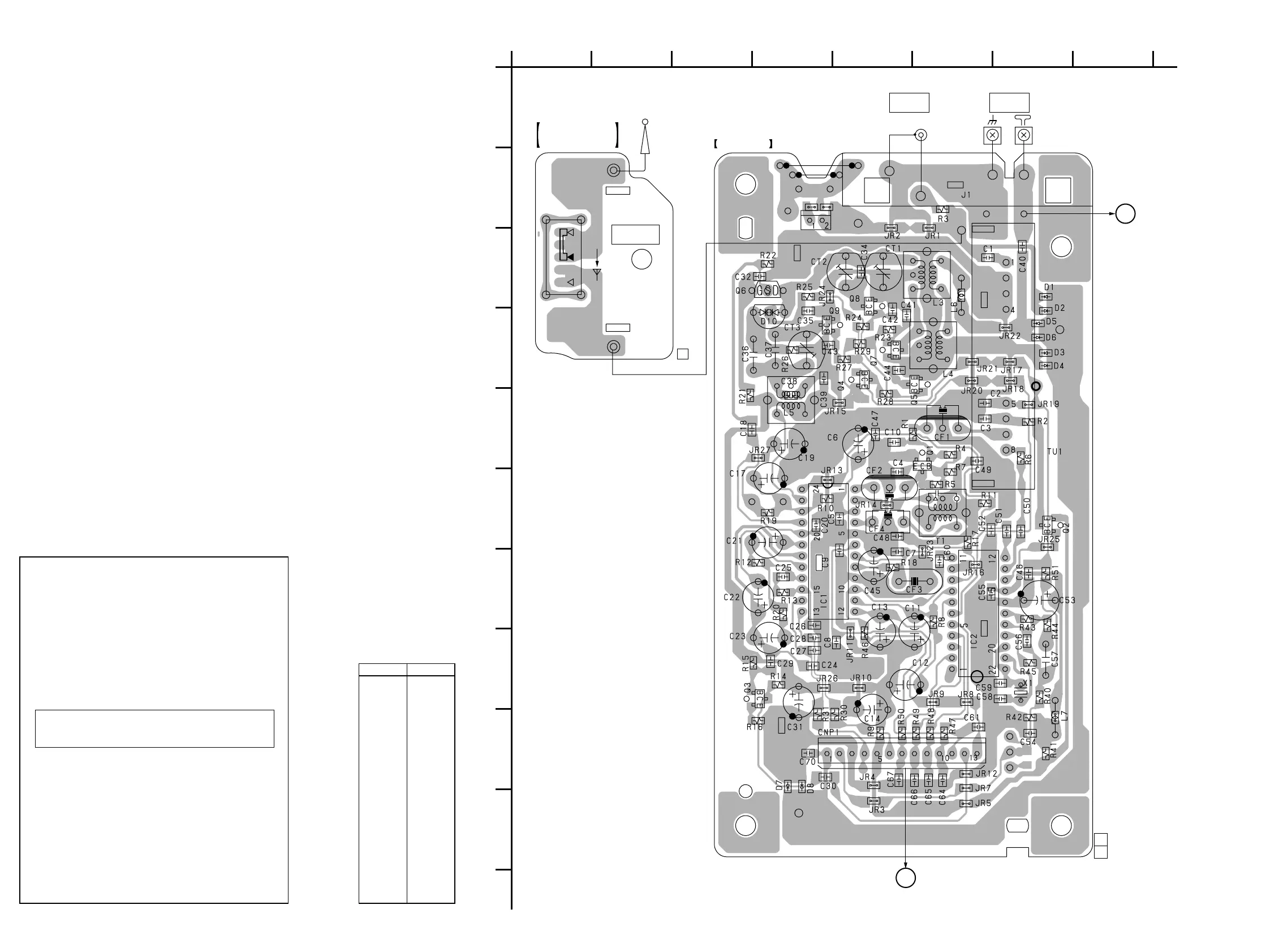
6-6. PRINTED WIRING BOARDS — TUNER SECTION —
• Refer to page 24 for Circuit Boards Location.
D1 D-7
D2 D-7
D3 D-7
D4 D-7
D5 D-7
D6 D-7
D7 J-4
D8 J-4
D10 D-4
IC1 G-4
IC2 H-6
Q1 F-6
Q2 G-7
Q3 H-4
Q4 D-5
Q5 D-6
Q6 C-4
Q7 D-5
Q8 C-5
Q9 D-4
• Semiconductor
Location
Ref. No. Location
Common Note on Printed Wiring Boards:
• X : parts extracted from the component side.
•
f
: internal component.
• b : Pattern from the side which enables seeing.
Common Note on Schematic Diagram:
• All capacitors are in µF unless otherwise noted. pF: µµF
50 WV or less are not indicated except for electrolytics
and tantalums.
• All resistors are in Ω and
1
/
4
W or less unless otherwise
specified.
•
f
: internal component.
• C : panel designation.
• U : B+ Line.
• H : adjustment for repair.
• Voltages are taken with a VOM (Input impedance 10 MΩ).
Voltage variations may be noted due to normal produc-
tion tolerances.
• Waveforms are taken with a oscilloscope.
Voltage variations may be noted due to normal produc-
tion tolerances.
• Circled numbers refer to waveforms.
• Signal path.
F : FM
f : MW/LW
J : CD
Note: The components identified by mark 0 or dotted line
with mark 0 are critical for safety.
Replace only with part number specified.
(Page 44)
(Page 44)
 Loading...