– 7 –
SECTION 3
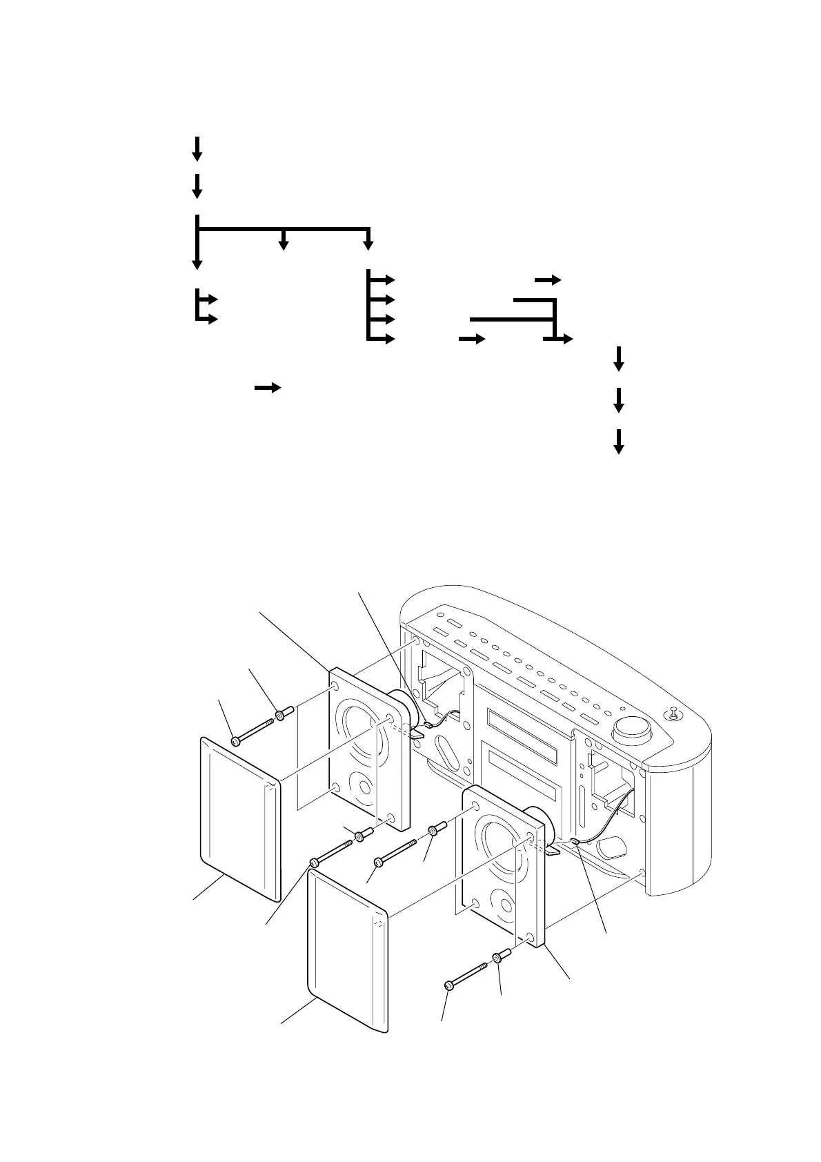
DISASSEMBLY
Note : This set can be disassemble according to the following sequence.
Note : Follow the disassembly procedure in the numerical order given.
3-1. “NET SUB ASSY, SARAN”, SPEAKER (FRONT) SUB ASSY
Set
“Net Sub Assy, Saran”, Speaker (Front) Sub Assy
Cabinet, Front
CD Block Assy
Top Cabinet Assy
Volume Board
H/P Board, Switch (1) Board,
Switch (2) Board
TU Board, EXT ANT Board “Cover, Heat Sink”, Line Board
FL Board, Lamp Board
Control Board
Main Board CD Board CD Block Section
Tray Assy, CD
Loading Board
Optical pick-up, Pick-up Relay Board
Power Board,
REG Board
Loop Antenna CL/Receiver Board
1 net sub assy (L), saran
6 speaker (front)
sub assy (L)
qd speaker (front) sub assy (R
7 CN304
qf CN304
8 net sub ass
R
, saran
2 BVTP 3x55
3 bush, net
qs bush, net
0 bush, net
5 bush, net
qa BVTP 3x55
9 BVTP 3x55
4 BVTP 3x55