Installation
Electrical Terminals
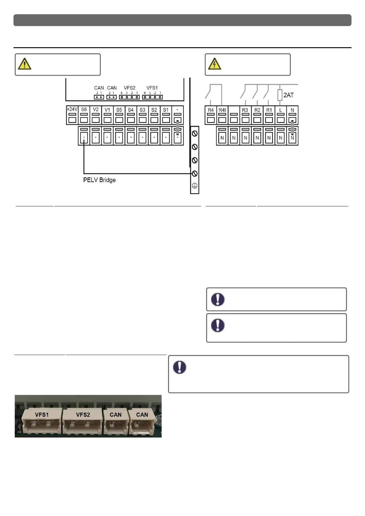
Low voltages
max. 24 VAC / DC
Mains voltages
230 VAC 50 - 60 Hz
Terminal: Connection for:
- GND bridge on the lower ground terminal block
S1 Temperature Sensor 1
S2 Temperature Sensor 2
S3 Temperature Sensor 3
S4 Temperature Sensor 4
S5 Temperature Sensor 5
V1 0-10V / PWM signal output e.g. for controlling high-effi-
ciency pumps
V2 0-10V / PWM signal output e.g. for controlling high-effi-
ciency pumps
S6 Temperature Sensor 6 (outdoor)
+ Terminal/
Voltage out-
put
24V voltage output
Max. load by external devices 24V / 6W
The connection of the ground wire is made at the lower gray terminal
block.
Terminal: Connection for:
N Neutral conductor N
L Network outer conductor L
R1 Relays 1
R2 Relays 2
R3 Relays 3
R4| Relay 4 | (potential-free contact)
R4 Relay 4 (potential-free contact)
The neutral conductor N must be connected to the N ter-
minal block.
The PE protective conductor must be con-
nected to the PE metal terminal block!
For high-efficiency pumps with 0-10V / PWM
signal input, the power can be provided (V1
/ V2 parallel operation) over a free relay.
On the control board
VFS1 Grundfos Direct Sensor
"Connection of PWM pumps"
PWM pumps are connected to the controller with 2 wires 1)
PWM Input (default: brown) 2) GND (default: blue). Some
pumps have a third wire (PWM Output Signal (default: black)).
This is not used for the connection!
VFS2 Grundfos Direct Sensor
CAN CAN bus connection (1=high,2=low)
CAN CAN bus connection (1=high,2=low)
12