Smart grid 1/ PV contact
A sensor input can be set here, which can be used as Smart grid terminal 1 for interference by the energy supplier or as a PV contact for
a photovoltaic system. This sensor is observed to "short circuit" (PV-Contact closed). If the PV-Contact is closed, the mode of this func-
tion is changed to "comfort" and operated at the comfort temperature set for the comfort function. This also applies in the case that the
mode "comfort" of the function currently has no time release.
Information about the operation and the connection of PV-contact, refer to the technical description of your PV system.
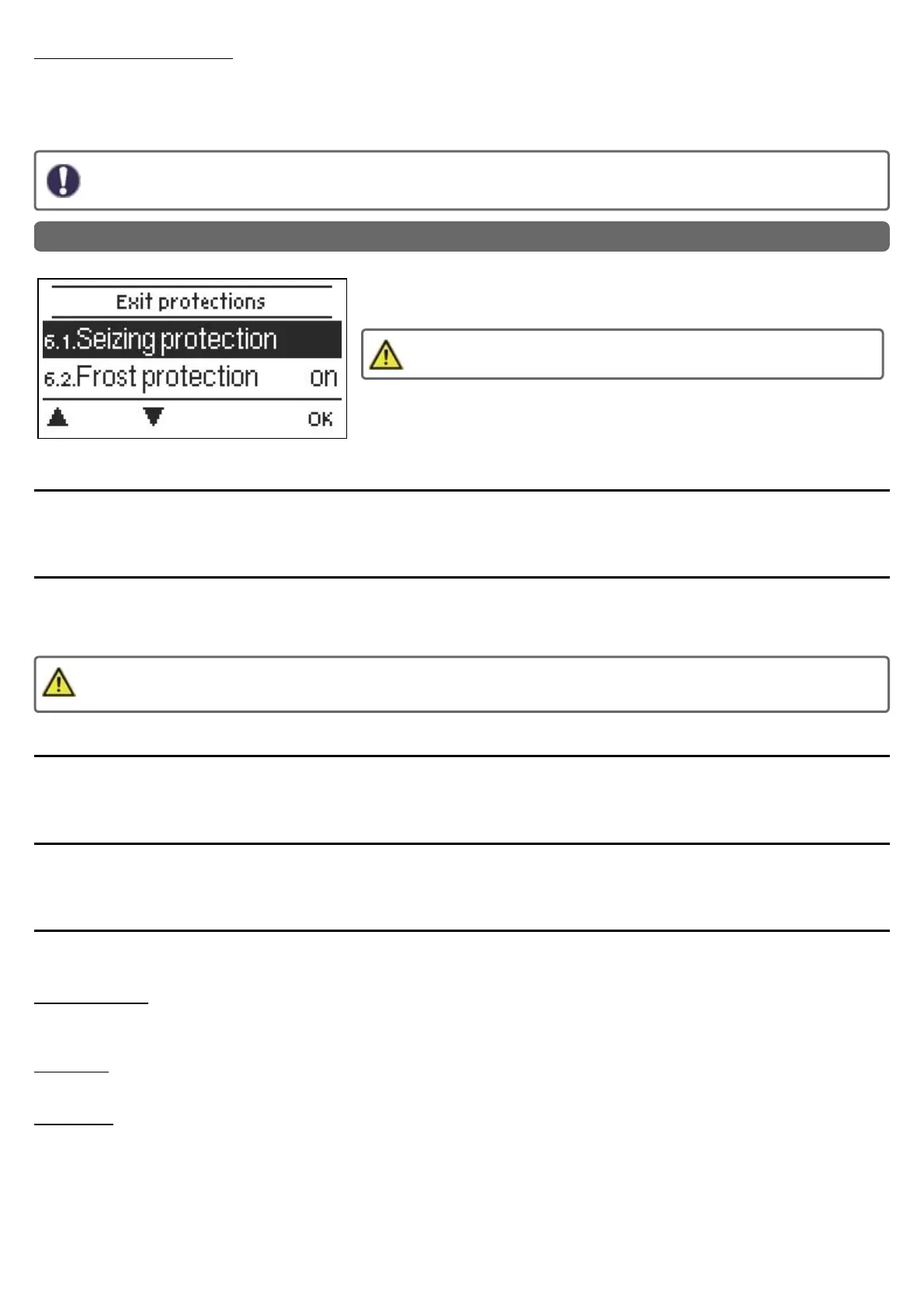
6. Protective Functions
The 'Protective functions‘ can be used by specialists to activate and set various pro-
tective functions.
By no means does the controller replace the safety appliances on site!
Seizing Protection
If the anti-seizing protection is activated (daily, weekly, off), the controller switches the heat pump and the mixer on/off at 12:00 noon for
5 seconds to prevent seizing of the pump/valve after long periods of inactivity.
Frost Protection
If the external temperature on sensor S1 goes below 1 °C and the heating circuit is turned off, the heating circuit will automatically be
turned on if the frost protection is activated and the reference flow temperature is set at the minimum flow temperature set under See "
Min. Flow " on page 34. As soon as the outdoor temperature exceeds 1 ° C, the heat circuit is switched off again.
Switching the frost protection function off or setting the minimum flow temperature too low can lead to severe damage to the
system.
Discharge Protection
With activated buffer discharge protection, the heating circuit is switched off as soon as the buffer temperature undershoots the min. flow
temperature. flow temperature. Every 5 minutes, the system checks if the flow temperature has been reached.
Dew point correction
Activate or deactivate. Activated dew point correction corrects the heating circuit flow temperature in cooling mode and switches off the
heating circuit when the temperature falls below the dew point in order to prevent condensation.
Pressure Monitoring
In this menu, the system pressure monitoring can be activated through a direct sensor. A message is displayed
and the LED flashes red when the pressure drops below the minimum or exceeds the maximum.
RPS1 / RPS2
In this menu, you can adjust which pressure sensor model is being used. Please note: If e.g. VFS1
is connected, RPS1 will be hidden
RPS Min
Minimum pressure. If this pressure is not met, the controller emits an error notification and the red LED flashes.
RPS Max
Maximum pressure in the system. If this pressure is exceeded, the controller emits an error message and the red LED flashes.
38