SORENSEN DCS SERIES MANUAL INSTALLATION and OPERATION
2-19
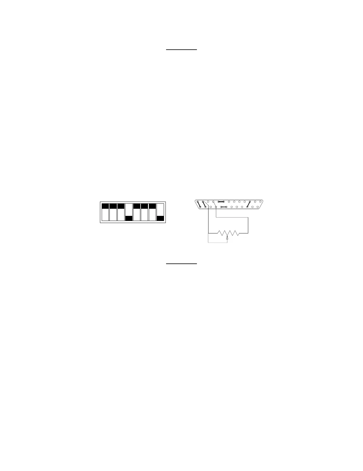
Switch SW1
SW1-1 Off (Open)
SW1-2 Off (Open)
SW1-3 Off (Open)
SW1-4 On (Closed)
SW1-5 Off (Open)
SW1-6 Off (Open)
SW1-7 Off (Open)
SW1-8 On (Closed)
Switch SW1 and Connector J3 Configuration
for Resistive Programming of the Output Voltage
(J3 sense line, OVP and current control jumpers shown set for local operation)
To program the output current limit, set switches SW1-1 and SW1-2 open (default factory setting) and remove
the jumpers connecting pins 10 to 11 and 22 to 23 on connector J3. Connect pins 10 and 22 to the
counterclockwise end of the 5k potentiometer and connect the tap and clockwise end of the potentiometer to pin 12.
Adjusting the tapped resistance from 0-5k will vary the current limit from 0-100% of the rated output.
SW1-1
SW1-2
SW1-3
SW1-4
SW1-5
SW1-6
SW1-7
SW1-8
CLOSED
CCW
1312
25
10
22
1
14
OPEN
Switch SW1
SW1-1 Off (Open)
SW1-2 Off (Open)
SW1-3 Off (Open)
SW1-4 On (Closed)
SW1-5 Off (Open)
SW1-6 Off (Open)
SW1-7 Off (Open)
SW1-8 On (Closed)
Switch SW1 and Connector J3 Configuration
for Resistive Programming of the Output Current Limit
(J3 sense line, OVP and voltage control jumpers shown set for local operation)
www.valuetronics.com