SORENSEN DCS SERIES MANUAL DRAWINGS and SCHEMATICS
6-1
SECTION 6. DRAWINGS AND SCHEMATICS
6.1 General
This section contains drawings and schematic diagrams for the DCS 1 kW power supply. The schematic diagrams should
be used to understand the theory of operation and also be used as an aid in troubleshooting the unit.
6.2 Drawings and Schematics
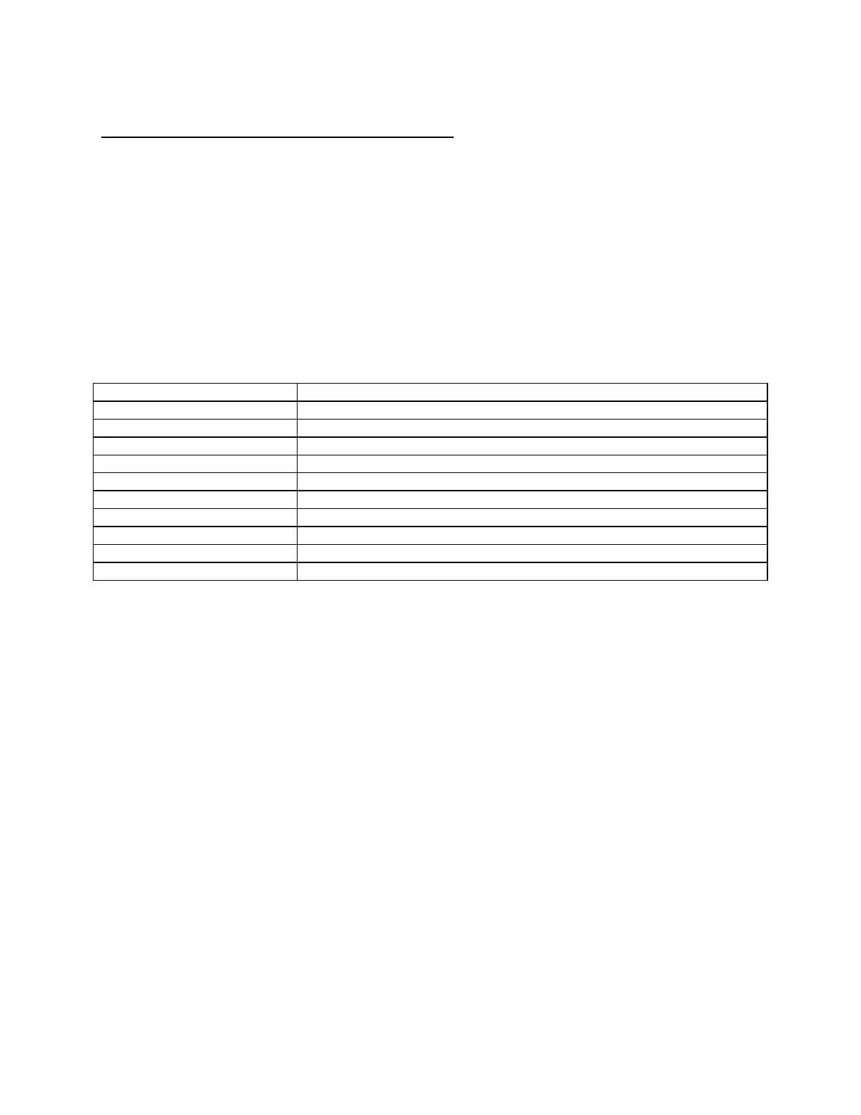
Table 6-1 provides a listing of the Drawings and Schematics included in this section and Table 6-2 provides a
Drawings/Schematics by Model Number matrix.
Table 6-1. DCS 1 kW Drawings/Schematics
Number Assembly
1066830 Output PCB Assembly Drawing
1066832 Rectifier PCB Assembly Drawing
1068573 Rectifier PCB Assembly Drawing
5360726 Rectifier PCB Assembly Drawing
5360800 Final Assembly Drawing
5360801 Front Panel PCB Assembly Drawing
5360802 Mother PCB Assembly Drawing
6360726 Rectifier PCB Schematic
6360801 Front Panel PCB Schematic
6360802 Mother PCB Schematic
www.valuetronics.com