INSTALLATION and OPERATION SORENSEN DCS SERIES MANUAL
2-18
SW1-1 SW1-2 PROGRAMMING VOLTAGE
OPEN OPEN 0-5Vdc and Local Mode
CLOSED CLOSED Not Used
CLOSED OPEN 0-10Vdc
OPEN CLOSED 0-100mV
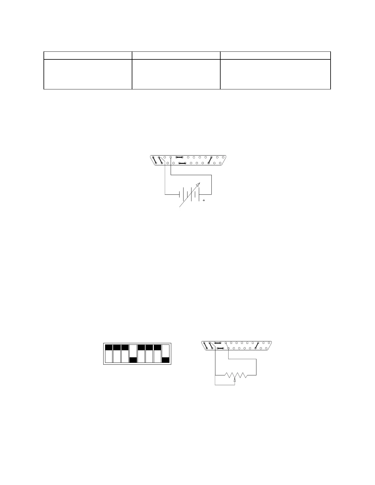
To remotely program the output current limit, set switches SW1-1 and SW1-2 as shown above, remove the jumpers
connecting pins 10 to 11 and 22 to 23 of connector J3 and connect the external voltage source between pins 10
(positive) and 12 (return). Varying the voltage source from 0-100% causes the current limit to vary from 0-100%
of the rated maximum.
1312
25
10 1
14
Connector J3 Configuration
for Remote Programming of the Output Current Limit
(J3 sense line, OVP and voltage control jumpers shown set for local operation)
2.11.2 Programming With an External Resistance
The output voltage and current limit can be programmed using a 5k ohm external potentiometer.
To program the output voltage, set switch SW1-3 open (default factory setting) and remove the jumpers
connecting pins 8 to 9 and 20 to 21 on connector J3. Connect pins 9 and 21 to the counterclockwise end of the 5k
potentiometer and connect the tap and clockwise end of the potentiometer to pin 12. Adjusting the tapped
resistance from 0-5k will vary the output voltage from 0-100% of the rated output.
SW1-1
SW1-2
SW1-3
SW1-4
SW1-5
SW1-6
SW1-7
SW1-8
CLOSED
CCW
1312
25
9
21
1
14
OPEN
www.valuetronics.com