833 User Guide
33
ROUTING SL-2 SOURCES TO CHANNELS
The SL-2 has a total of 12 sources, up to eight channels of wireless
from the two slots (A1-A4, B1-B4) plus four channels of AES from the
rear panel TA3 ports. Only eight of these sources can be used at any
one time.
To route an SL-2 Source to a channel, access a channel’s source
screen and select from A1-A4, B1-B4, AES 1-4. When A1-A4, B1-B4
are selected as source, use the */** toggle as a shortcut to the
selected receiver’s setup screen.
For SL-2 A1-A4, B1-B4, and AES 1-4 sources, channel trim gain range
is -20 to 50 dB.
RF OVERLOAD LEDS Each antenna input on the front panel of the
SL-2 has an associated LED that displays incoming RF level status.
Red = Overload
Orange = approaching overload
Off = no overload
To disable the LEDs go to SL-2 Options>Antenna LEDs and toggle to
Off.
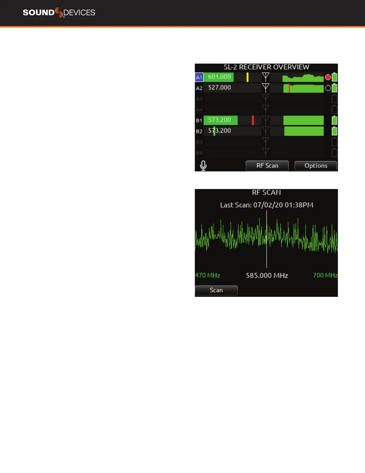
SL-2 RECEIVER OVERVIEW Select the SuperSlot menu to enter
the SL-2 Receiver Overview screen which displays information for all
receivers connected to the SL-2. Press the HP knob while holding
Meter to quickly access the Receiver Overview screen
A1-A4, B1-B4 Use the Select knob to scroll and select a SL-2
channel to access the individual Receiver Setup screen. See Receiver
Setup Screen for more details.
POST-TRIM CHANNEL METERING Displays the post-trim audio
level of the Scorpio channel receiving audio from the SL-2 source.
When the SL-2 source is not routed to a Scorpio channel, no signal is
displayed on the meters.
RF FREQUENCY Displays the frequency of the receiver in MHz.
TX BATTERY LEVEL: Displays the battery level of the paired TX, if
applicable.
Green = over 50%
Yellow = over 20%
Orange = over 10%
Red = less than 10%.
TX RECORD STATUS Indicates the record status of the paired trans-
mitter, if applicable.
Red = recording
TX STATUS BOX (A10-TX only): Indicates paired TX mute, Limiter, and
Audio Overload status.
Blue with ‘M’ = TX Mute On
Yellow with ‘L’ = TX Limiting
Red with ‘O’ = TX Audio Overload
RF LEVEL HISTORY Displays the RF level over a period of time.
Duration of RF History is set in SL-2 Options>RF History Duration
parameter from 30 to 600 seconds in 10 s steps, default duration is
30 s. The taller the green bar, the healthier the received RF signal. A
red bar signies receiver RF overload (A10-RX only).
RX ANTENNA ICON Indicates RF signal status.
Solid white = locked to antenna signal
Flashing white = antenna signal unlocked
Solid Red = antenna signal overload
Gray = no receiver detected
RF SCAN Instigates an RF Scan of the environment using both slot
receivers. Use the */** toggle switch to start the scan.
OPTIONS Access the SL-2 Options menu by using the Rtn/Fav toggle
switch.
 Loading...