Hardware Installation
SY-7VBA133U
40
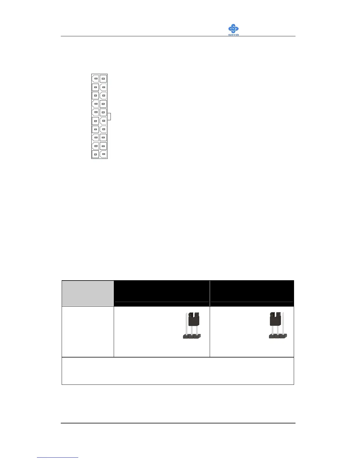
3.3V
-12V
GND
PS-ON
GND
GND
GND
-5V
5V
5V
3.3V
3.3V
GND
5V
GND
5V
GND
PW-OK
5VSB
12V
ATX Power
Please install the ATX power according to the following pin assignment:
Pay special care to the directionality.
2-3.4 CMOS Clear (JP5)
In some cases the CMOS memory may contain wrong data, follow the
steps below to clear the CMOS memory.
1. Clear the CMOS memory by momentarily shorting pin 2-3 on jumper
JP5. This jumper can be easily identified by its white colored cap.
2. Then put the jumper back to 1-2 to allow writing of new data into
the CMOS memory.
CMOS
Clearing
Clear CMOS Data Retain CMOS Data
JP5 Setting
Short pin 2-3 for
at least 5
seconds to clear
the CMOS
Short pin 1-2
to retain new
settings
Note: You must unplug the ATX power cable from the ATX power
connector when performing the CMOS Clear operation.
12 3
123

 Loading...