91369 Service Manual 4-13
Maintenance
Caution:
• Never pull on the flex cable. This may damage the cable end or the connector.
• Take care when handling cables and connectors. They are fragile and can be damaged.
Note:
• Due to the short length of the video cable, remove it prior to fully opening the case.
• Proper operation of the monitor depends upon correct cable re-insertion following disassembly. Ensure
that the flex cable is aligned properly and fully inserted into the connector prior to locking the connector
tab down.
3 Remove the touchscreen five-wire cable from the CPU PCBA.
4 Remove the power switch/monitor assembly by sliding the “ZIF” connector locking mechanism outward,
then removing the cable from the socket.
5 Unlatch the touchscreen cable and remove the eight 6-32-inch × 1/4-inch screws (three along the top, three
in the center, and two at the bottom of the PCBA).
If you are replacing the front bezel, proceed to the next section (Replacing the Display or Touchscreen
Assembly, Backlight Inverter, and Power Monitor Assemblies) for removal of the remaining front bezel
assembly components.
Replacing the Display or Touchscreen Assembly, Backlight Inverter, and
Power Monitor Assemblies
1 Remove the front bezel assembly as described in Removing the Bezel Assembly on page 4-11.
2 Remove the four screws securing the display assembly to the front bezel and carefully lift the assembly from
the bezel.
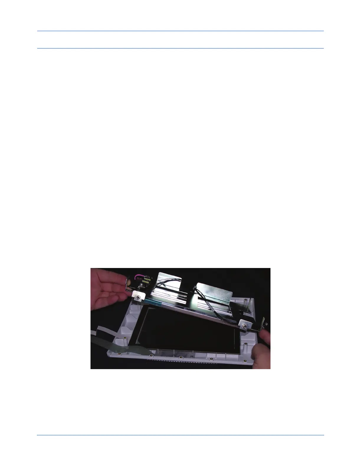
Figure 4-6: Removing the touchscreen display bracket
Caution:
The glass touchscreen may stick to the front of the display bracket. Do not allow it to fall off of the
bracket during removal.
3 Remove the four screws securing the display to the brackets.
 Loading...