8999151EN: v1 11/03/2021
35
Original instructions (ENGLISH)
Website: www.spearheadmachinery.com
It is important to assess the machine to ensure that it is of the correct specification ordered from Spearhead or
local Spearhead dealer. Information with regards to the specification of the machine can be found on the
machines serial plate. Guidance to the location of the serial plate can be found in Section 1.3.
Before use it is important to inspect the machine following the guidance in this operators manual to ensure it is
correctly set-up and is suitable for the attaching tractor using the inspection guidance sheet in Section 5.8.
3.3 PTO Shaft
3.3.1 PTO Setup & Adjustment (first use)
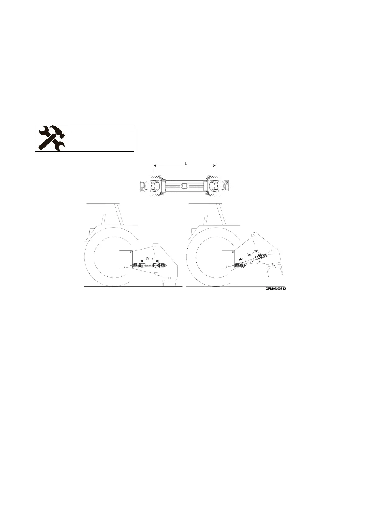
Figure 3.2 –Input Shaft Overlap
The PTO of your machine will be delivered as it left the manufacturer, so will require to be shortened to give the
correct effective length between the machine and the power take-off of the tractor.
In order to determine the correct length of the finished driveline (L), hook the machine to the tractor, leaving the
machine on the ground and proceed to install the two uncoupled/unprotected semi-shafts to their respective
tractor/machine PTO’s; see Figure 3.2. It is important that when fitting the two semi-shafts, the distance between
the joints, “Dmin”, is less than the original length “L” of the closed removed input shaft. This is so that the input
shaft tubes aren’t “bottomed”. For guidance on fitting input shafts; see Section 4.4.1.
When using the machine and moving in between the lowest “working” position and the highest, most raised
“transport” position, the distance between the joints will further shorten. This is “Ds”. By carrying out a “Bottoming
Out Test” as stated in Section 3.3.2, verify any interference of the outer tube with the yoke inner tube and
establish how much the outer tube needs to be shortened.
The input shaft should be shortened to ensure:
• At least 25mm (1”) clearance at the between the end of the shaft and the universal joint
• At least 1/3 of the shafts length overlap engagement between the two tube halves
Check and ensure that the shaft has been sufficiently maintained and prepared before proceeding to use using
the machine following the guidance given in Section 5.2.2.