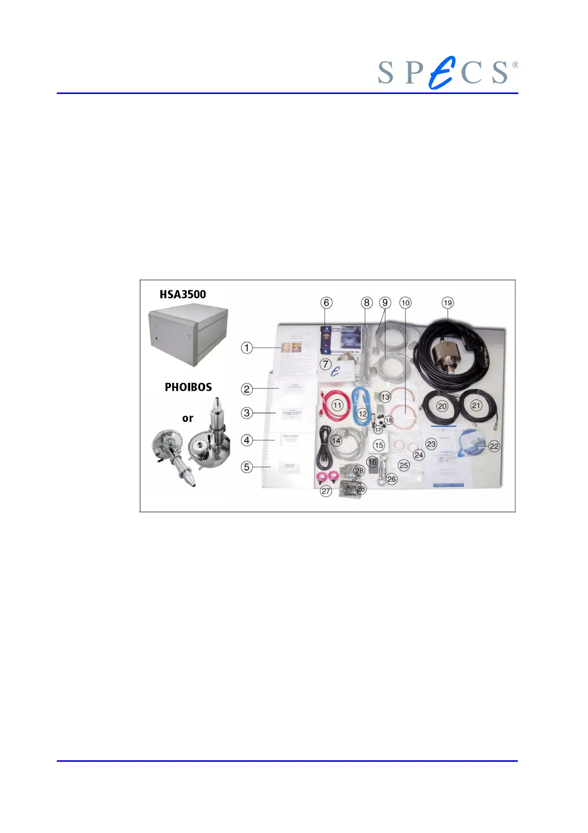
Components and Connections
19. Analyzer box with filter unit (cube or cylinder shape) , fixed cable
20. SHV-cable ChannelBase
21. SHV-cable ChannelHV
22. SpecsLab2 Installation CD
23. Specification (Test Report)
24. Pair of DN40CF copper gaskets
25. Pair of DN16CF copper gaskets
26. Two Lugs for analyzer lift
27. Two Lugs for analyzer support (only PHOIBOS 150
28. Screws for lens flange
(screws and nuts for PHOIBOS 100 and bolts and nuts for PHOIBOS 150)
Figure 1: Package Contents
2.2 Electrical Connections
The electrical connection diagram is shown in figure 2, page 7. The connection to the
analyzer and the detector are supplied by two multi-pin vacuum feedthroughs that are
designed for high voltages up to 5 kV. More detailed descriptions are given in section
and section 8.4 .
All devices must be switched off before connecting or removing cables.
6 PHOIBOS
 Loading...