Spectrometer
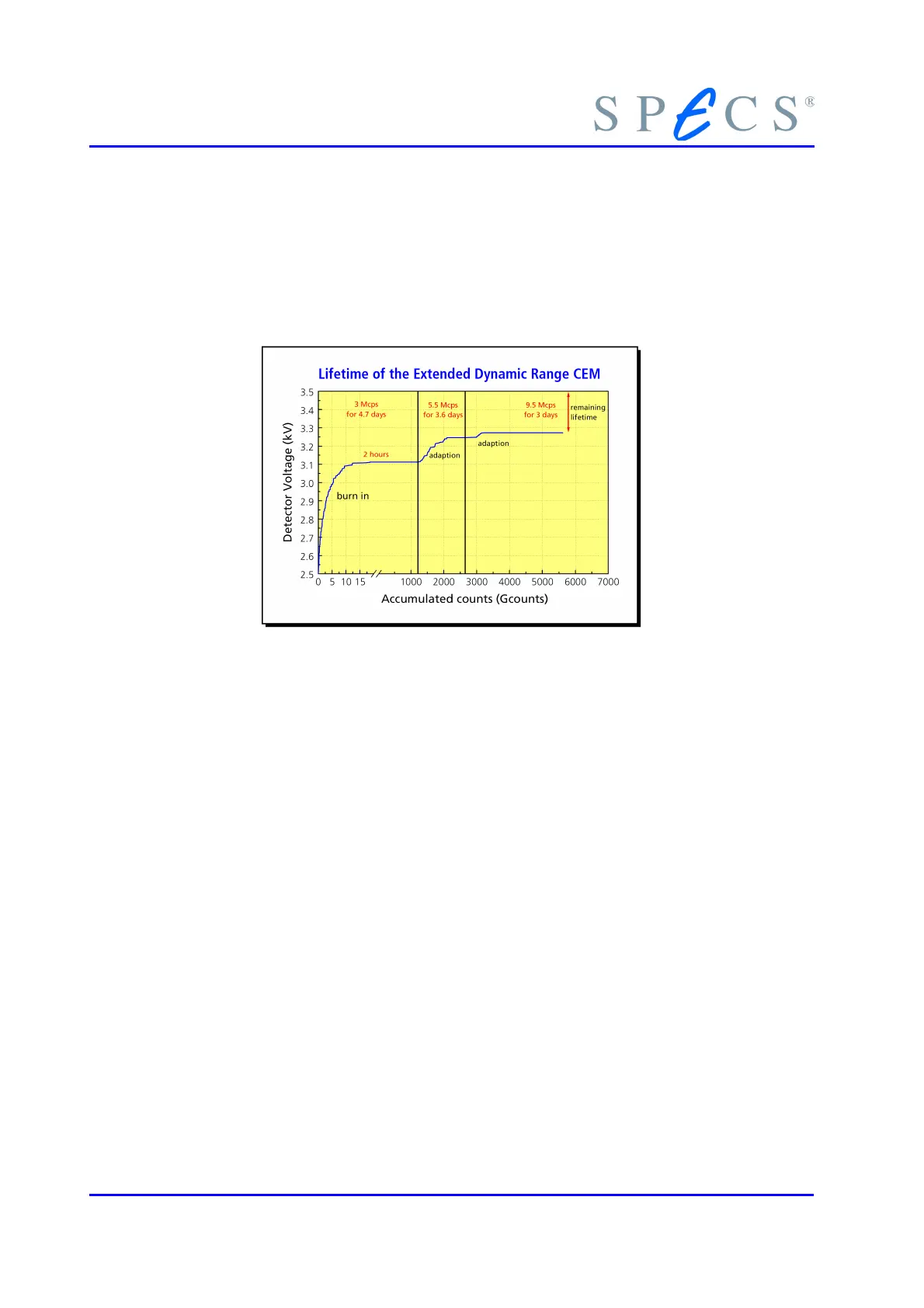
surface of the channel. The gain is governed by the detector voltage and the condition
of the emissive layer. The condition of this layer changes with usage and to compensate
for a drop in emissive quality of the surface, an increased detector voltage can be ap-
plied keeping the overall gain constant. If the detector voltage has reached the limit of
3.5 kV the CEM is at the end of its life and needs replacing.
Figure 16: Lifetime of the Extended Dynamic Range CEM
● While a CEM is not counting, residual gases in the system are adsorbed onto the
channel walls, which are kept clean by electron bombardment during opera-
tion.
● When initially running a new CEM it needs approximately 20 × 10
9
counts for
conditioning. Once properly conditioned, or “burned in”, the surface on the
semiconducting glass channel is quite stable.
● The test results suggested that accumulations to 5 × 10
12
counts and higher can
be expected without serious degradation.
● The extended range CEM’s are suitable for extremely high count rates without-
serious degradation.
3.5.3.2 Linearity of the CEM’s
Inadequate design may cause electron analyzers to show non-linear behavior. For an
ideal counter with a non-extended dead time τ the measured count rate N’ and the
true count rate N are given by
(20)
With the PHOIBOS SCD analyzer the count rate as a function of the Auger electron
beam current has been measured using both the standard and extended dynamic range
CEMs. For a non-extended dead time counter the ratio N’1 / N’2 of two spectra N’1 and
N’2 (measured at two different beam currents A × I and I) the spectral ratio is given by
30 PHOIBOS
 Loading...