Multiplier
● Disconnect the cables.
● Note the orientation and alignment of the defective channeltrons.
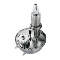
● Release the screws which are fixing the ceramic rods. Release only one of the
adjustment screws. Do not change the other screws, this fixes the position for
the channeltrons with respect to the body when rebuilding the assembly(figure
37, page 83).
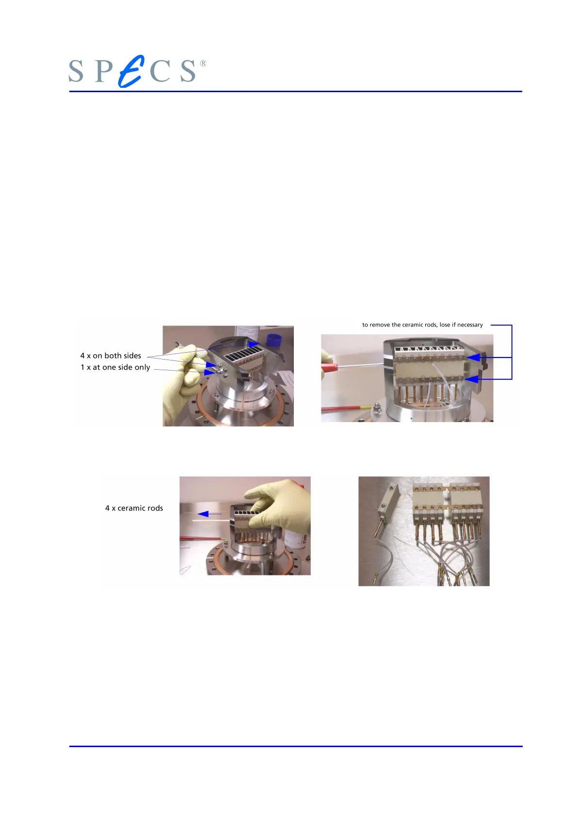
● Pull back the ceramic rods until the replacement of the channeltron is possible
(figure 38, page 83). If the ceramic rod is stuck, try to loosen the screws of each
channeltron a bit.
● Remove the channeltron.
● Put the new channeltron in place and rebuild in reverse order.
● Carefully fasten the connections with the screws. Note: A bad contact means
noisy channeltron!
● Check all channeltrons for proper mounting.
● Check all electrical connections (Figure 33: Schematics of the 12-pin Analyzer
Feedthrough, page 72).
Figure 37: Screws fixing the ceramic rods and adjustment crew
Figure 38: Pull back the Ceramic Rods, Remove the Channeltron
10.2.2.3 Mounting the Detector Flange
● Mount the detector flange in reverse order.
● Check that there is no short circuit for all the pins of the detector supply feed-
through to each other and to ground.
PHOIBOS 83
 Loading...