Spectrometer
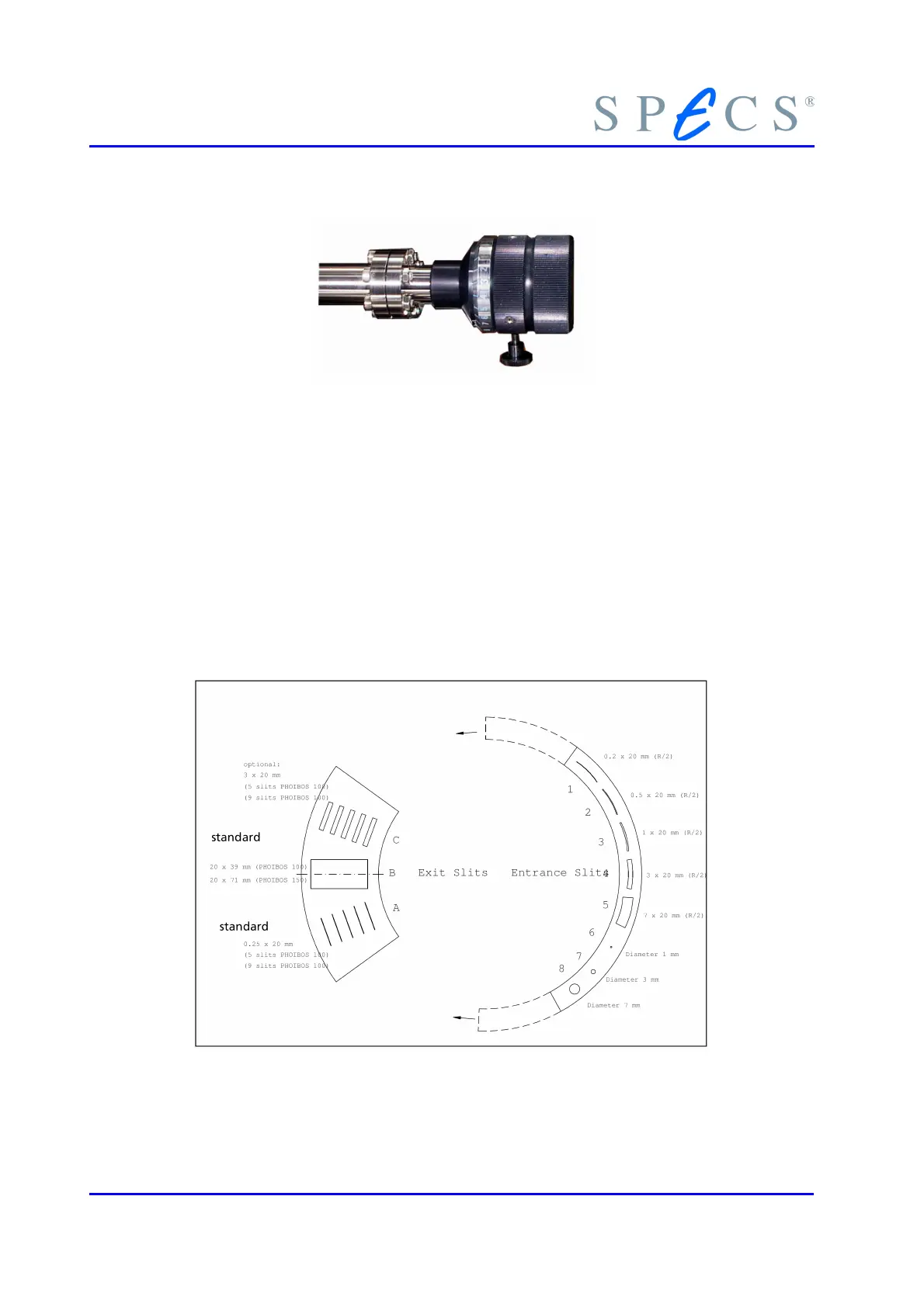
Figure 12: External Rotary Dial for Positioning
The indicators on the rotary dial are used for positioning, but it must be taken into ac-
count that the rotary dial has some backlash. The correct slit positions are defined by
spring loaded indexing balls. Because of the rotary feedthroughs backlash, rotate it
beyond the desired position until the indexing ball snaps in.
After positioning the dial, jog it back and forth to ensure that the index is probably en-
gaged. The correct positioning of the entrance slits can also be checked by looking
through the view port. In a configuration with two exit slits, the positioning of the exit
slit is not critical because of the end stops. In configurations with a third exit opening
please be aware that positioning of slit B can be tricky and require some practice. An
analyzer configured with two exit slits can be reconfigured on request.
Figure 13: Entrance and Exit Slit Rings (Slit Combination 4-B)
24 PHOIBOS
 Loading...