Offset Calibration with UPS
Note the voltage range used while measuring. For adjustment, the desired range
should be selected according to the used method : i.e. 40V, 400V, 1500V or 3500V in the
active method row of Analyzer settings (see SpecsLab2 menu ’Analyzer/Settings’).
1. Warm up the HSA3500 at least 10min. Switch off and on again to reboot and
force a startup calibration or manually perform the recalibration of the DACs
(section 7.2 on page 59).
2. Set the voltage range for the UPS measurement mode in the Menu
’Analyzer/Settings’, see Figure 26, to 40V.
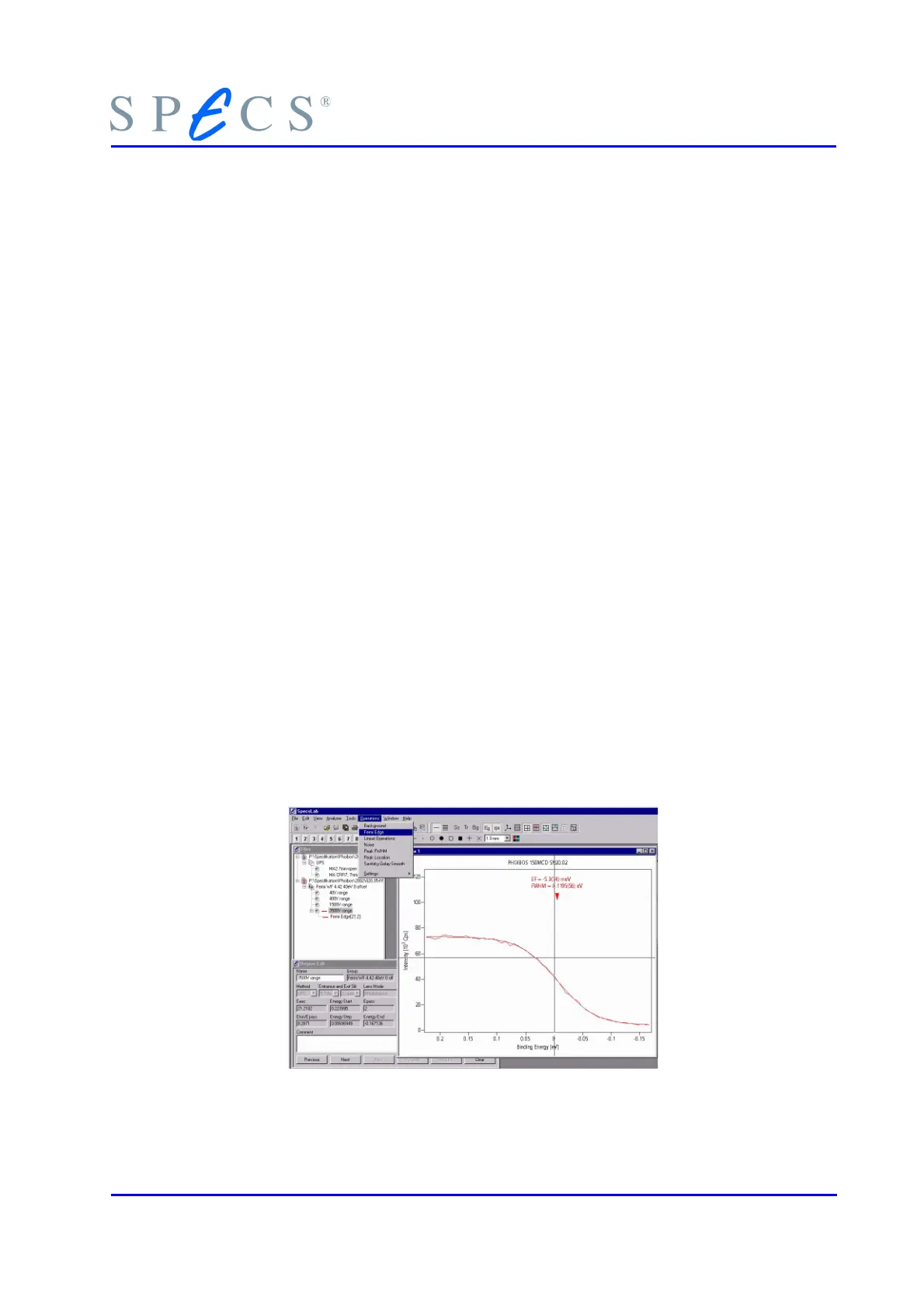
3. Switch to the binding energy scale. Measure the position of the fermi edge (e.g.
+0.2 to -0.2 eV binding energy, and select HeI (if He I of course is used) in the
dummy source of the Menu ’Analyzer/Settings’ Sources selected). (The tool Op-
eration/Fermi Edge in the SpecsLab2 program as well as the cursor and differ-
ence cursor cross (black/red cross icon, left/right mouse button) simplifies the
procedure.)
4. Note the comments given in section 7.4 , "Work Function Calibration with UPS"
on page 61.
5. Use this 40V range result as the reference point for the other voltage ranges.
6. Select one of the other voltage ranges (400/1500/3500V) in Menu ’Analyzer/Set-
tings’ and perform a Fermi edge measurement like for the 40 V range.
7. Compare the result with the 40V range spectra.
8. Calculate the energy difference between expected and measured Fermi edge
(the usual difference is less than 0.2 eV, more suggest a hardware error). Set the
offset for the selected voltage range (use binding energy values to get the cor-
rect polarity for the offset).
9. Set the offset of the used energy module to the calculated value in the menu
analyzer settings.
10. Measure again and repeat the procedure for each of the other desired voltage
ranges.
Note the advice given in section 7.2 , "Recalibrate the DAC Precision" on page 59.
Figure 30: Fermi Edge Operation
PHOIBOS 63
 Loading...