Components and Connections
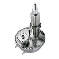
Figure 5: Analyzer Main Components and Voltage Principle
U0 main retardation voltage numerically equal to
- kinetic energy (Ekin) +pass energy (Ep) + workfunction (WF)
UChannel HV / Base anode / cathode potential for the channeltrons
UHV - UBase detector voltage
UChannelBase - U0 conversion voltage
LA..LE lens potentials
IH, OH inner / outer hemisphere
T1 to T10: electrodes of the multi mode transfer lens
S1: hemispherical capacitor entrance slit
S2: hemispherical capacitor exit plane
IH: inner hemisphere
OH: outer hemisphere
ro: nominal capacitor radius (100 or 150 mm)
C1 to C9: discrete collection, single / multichannel detector
(1, 5 or 9 channels)
single channel detection (SCD), multi channel detection (MCD)
10 PHOIBOS
 Loading...