Thermo E 200 / 320 8 Repair
809
8.11 Combustion chamber removal and
installation
Removal
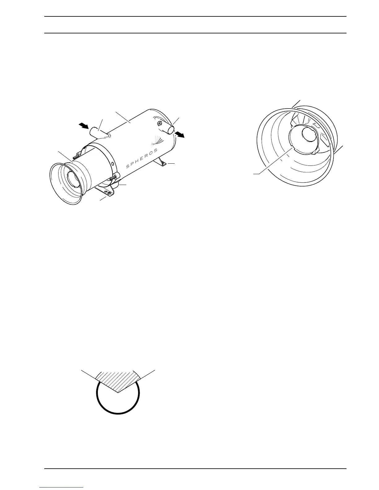
1. Remove burner (see 8.2).
2. Pull combustion chamber (1, Fig. 807) out of the heat
exchanger (2).
Installation
1. Slide combustion chamber (1, Fig. 807) into the heat
exchanger (2) as far as it goes.
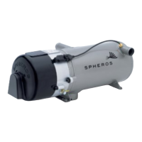
NOTE
– The combustion chamber should be inserted into
the heat exchanger in such a way that its welding
seam is positioned between 2 and 10 o clock (not
upwards!). A position change during mainte-
nance is permissible and affects the expected
service life of the combustion chamber positively.
– It should be ensured that none of the 4 cut-outs of
the combustion chamber head points vertically
downwards (see graphic below).
Dripping from nozzle fuel is so collected in a
reservoir between disc and burner head and will
be burned at the next burner operation instead to
soil the heater.
2. Install burner (see 8.2).
8.12 Heat exchanger removal and
installation
CAUTION
Combustion chamber and heat exchanger can be
very hot. If necessary, let them cool down.
Removal
1. Remove burner (see 8.2)
2. If necessary, remove temperature sensor (see 8.3).
3. Pull combustion chamber (1, Fig. 807) out of the heat
exchanger (2) (see 8.11).
4. If necessary, loosen the exhaust line clamp on the
exhaust outlet (3).
5. If existing, close water taps.
6. Loosen hose clamps on the coolant hoses, pull
coolant hoses from the coolant inlet (5) and the
coolant outlet (6) and seal with blank plugs. Caution if
coolant temperature is increased.
7. Remove screws and washers of the heat exchanger
stand (4).
8. Remove heat exchanger from the vehicle.
Installation
1. Bring heat exchanger (2, Fig. 807) into installation
position and mount stand (4) using screws, nuts and
washers to the vehicle according to the mounting
points used.
2. If necessary, secure the exhaust line using a clamp to
the exhaust outlet (3).
3. Fit coolant hoses onto the coolant inlet (5) and the
Fig. 807 Combustion chamber disassembly and
assembly
Fig. 808 Combustion chamber welding seam position
2
1
1 Combustion chamber
2 Heat exchanger
3 Exhaust outlet
4Stand
5 Coolant inlet
6 Coolant outlet
5
6
4
4
3
permissible
not permissible
Fig. 809 Cut-out positions on the combustion chamber
head
Cut-out positions
on the combustion
chamber head
in installed position