Waukesha Cherry-Burrell
®
Brand W70 Series Mix Proof Valves Installation
10/2023 95-03087 Page 13
Fittings
When using suitable fittings, Mix Proof valves with detachable
connections can be installed in a pipe system per the fitting
requirements. The valve must be installed free of tension. After
the valve is installed in the pipe system, attach the control air
hoses and connect the electrical supply.
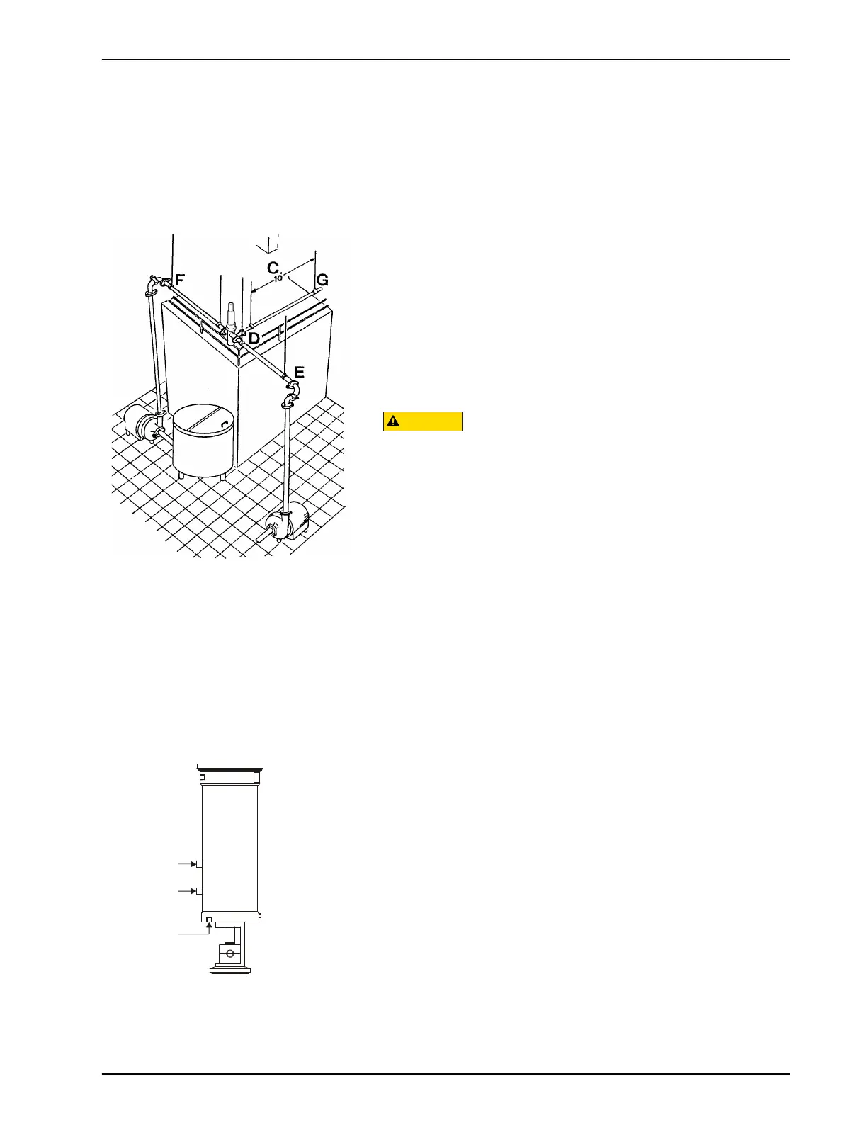
Pipeline Support
Install adequate supports to prevent strain on the fittings, valves
and equipment connections.
.
1. Install supports at least every 10 feet on straight runs of
piping. (Figure 2, item C).
2. Install supports on both sides of the valves as close as
possible to the connections. (Figure 2, item D).
3. Install supports at each change of pipeline direction. (Figure
2, item E and F).
4. For pipelines passing through walls, floors or ceilings, provide
at least 1 inch (25 mm) of clearance around the pipe to allow
for expansion and contraction. (Figure 2, item G).
In higher-temperature applications, ensure proper accommoda-
tion for thermal expansion in the pipeline design to minimize
stresses on the valve bodies. Excessive mechanical and thermal
stresses can distort and damage the valve bodies.
Installing Valve Manifolds
Install automatic valve manifolds with a uniform pitch for proper
drainage. Elevate one corner of the cluster and pitch 1/16" per
foot (1.59 mm per meter) if desired. Arrange the supports for the
floor-mounted valve manifolds to provide alignment of the inlet
and outlet lines.
Installing the Valve
1. If solenoids are mounted in a control top, connect the air
supply lines to “air in.” If solenoids are mounted externally
from the control top, connect the air lines as explained in
“Solenoid Valve Port Connections” on page 17.
2. Using caution, lift the actuator assembly and set the actuator
in the body assembly.
3. Lower the valve slowly into the body, making sure the lower
stem enters the lower bearing carrier.
4. Tightly clamp the yoke/body flange.
5. Connect the air lines to 1, 2 and 3, as shown in Figure 3, left,
and Figure 10 on page 17.
Figure 2 - Pipeline Support
Figure 3 - Solenoid Valve Port
Connections

 Loading...