Maintenance Waukesha Cherry-Burrell
®
Brand W70 Series Mix Proof Valves
Page 36 95-03087 10/2023
Actuator O-ring and
Bearing Replacement
The valve stems and actuator must be removed from the valve
body before servicing the actuator components.
Although WCB fully-maintainable actuators are designed with a
contained spring for safety, always use caution when handling
any piston/spring assembly as any compressed coil spring can
be extremely dangerous.
NOTE: Do not pressurize the actuator with air when the stems
are removed. This may tear the O-rings and cause the actuator to
leak air when it is re-assembled.
NOTE: If present, the control module must be removed to replace
the O-rings and bearings in the top of the cylinder assembly.
Please refer to control module publication 95-03083.
NOTE: For larger drawings and complete part lists, see “W71/
W73 Non-Seat Lift Actuator” on page 84 and “W72RS Non Seat
Lift Actuator” on page 88.
Removal of O-rings and Bearings, Non-Seat Lifting
Actuators
Non Seat Lifting Actuators
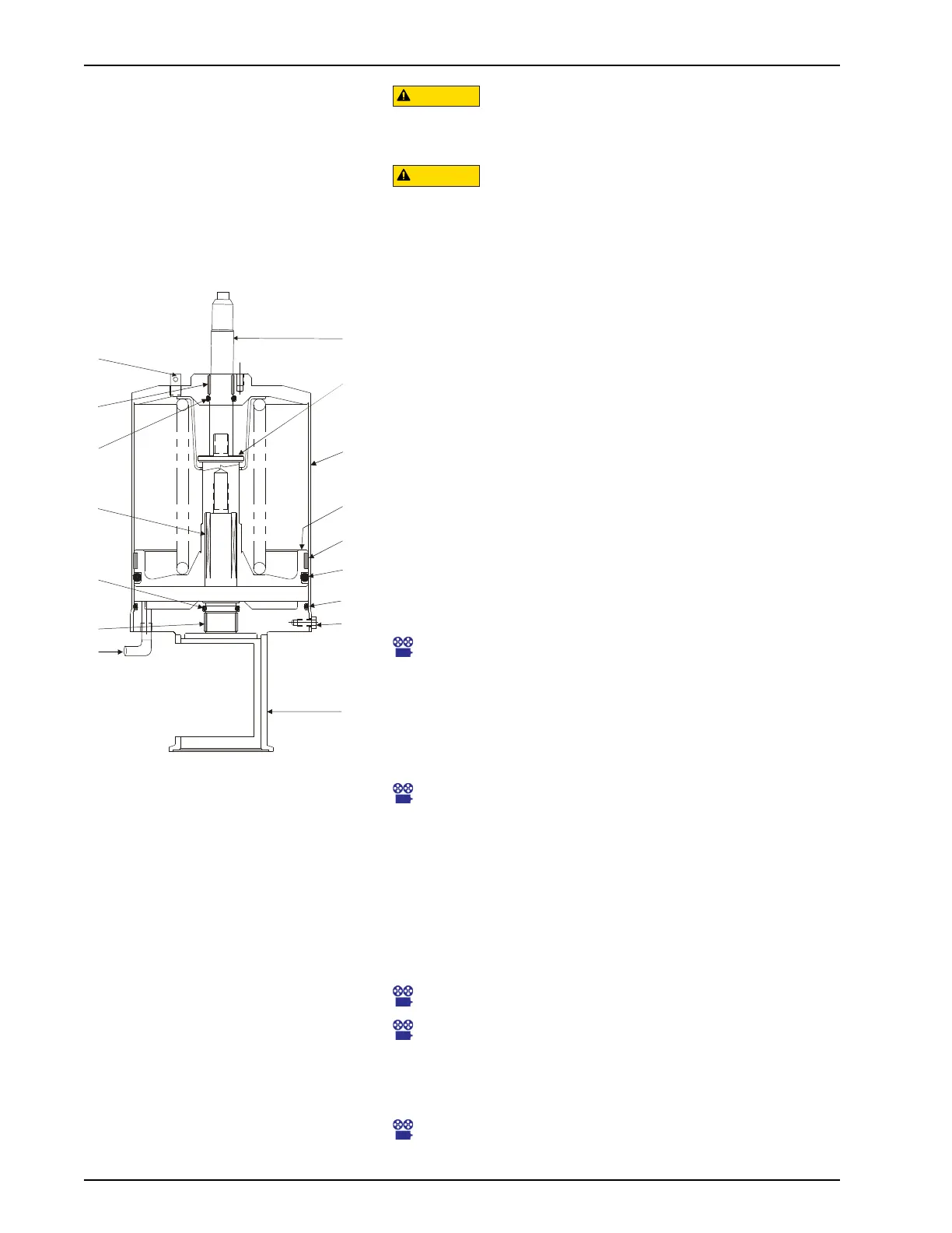
1. For non-seat lifting valves, remove the cap screws (Figure
35, item 9) and remove the yoke (item 12) from the cylinder
assembly. Set the yoke aside.
Maintenance Video 14: Actuator disassembly; lower
cartridge removal
2. Pull the piston and spring assembly (Figure 35, item 10) from
the cylinder assembly.
3. Inspect the four O-rings (Figure 35, items 6, 7, 8, and 11).
Replace them if they are worn or damaged.
Maintenance Video 16: Removal of main piston, lower seat
lift piston
4. Inspect the three bearings (Figure 35, items 5, 14, and 15). If
the bearing does not extend slightly above the edge of the
metal surface, replace the bearing.
5. The bearing is split to allow its removal from the groove.
Place a screwdriver or pick behind the bearing and pry it
away from the wall of the yoke or cylinder cap. A needle-nose
pliers can be used to grip the bearing for removal.
Maintenance Video 17: Main piston O-ring removal
Maintenance Video 18: Main piston O-ring replacement with
bearing
6. Assemble the stack components as shown in Figure 35.
Install the yoke and cap screws.
Maintenance Video 22: Using insertion sleeve for W71/W73
Actuators
Figure 35 - W71/W73 Actuator Assem-
bly (Non-Seat Lift Valve)
VA100-430
5
6
18
11
15
33
9
7
8
14
10
4
12
1,1a
13
31
NOTE: The bearing will be damaged
during removal and must be replaced
with a new bearing.
NOTE: Installation of the piston and
spring assembly on 4" actuators
requires a special sleeve to contain
the bearing on the piston while
installing the assembly. See Figure 37
and Figure 38 on page 38.

 Loading...