Waukesha Cherry-Burrell
®
Brand W70 Series Mix Proof Valves Maintenance
10/2023 95-03087 Page 25
Seat Cleaning Adjustment
Seat lifting models are factory set. See Figure 17 and Figure 18.
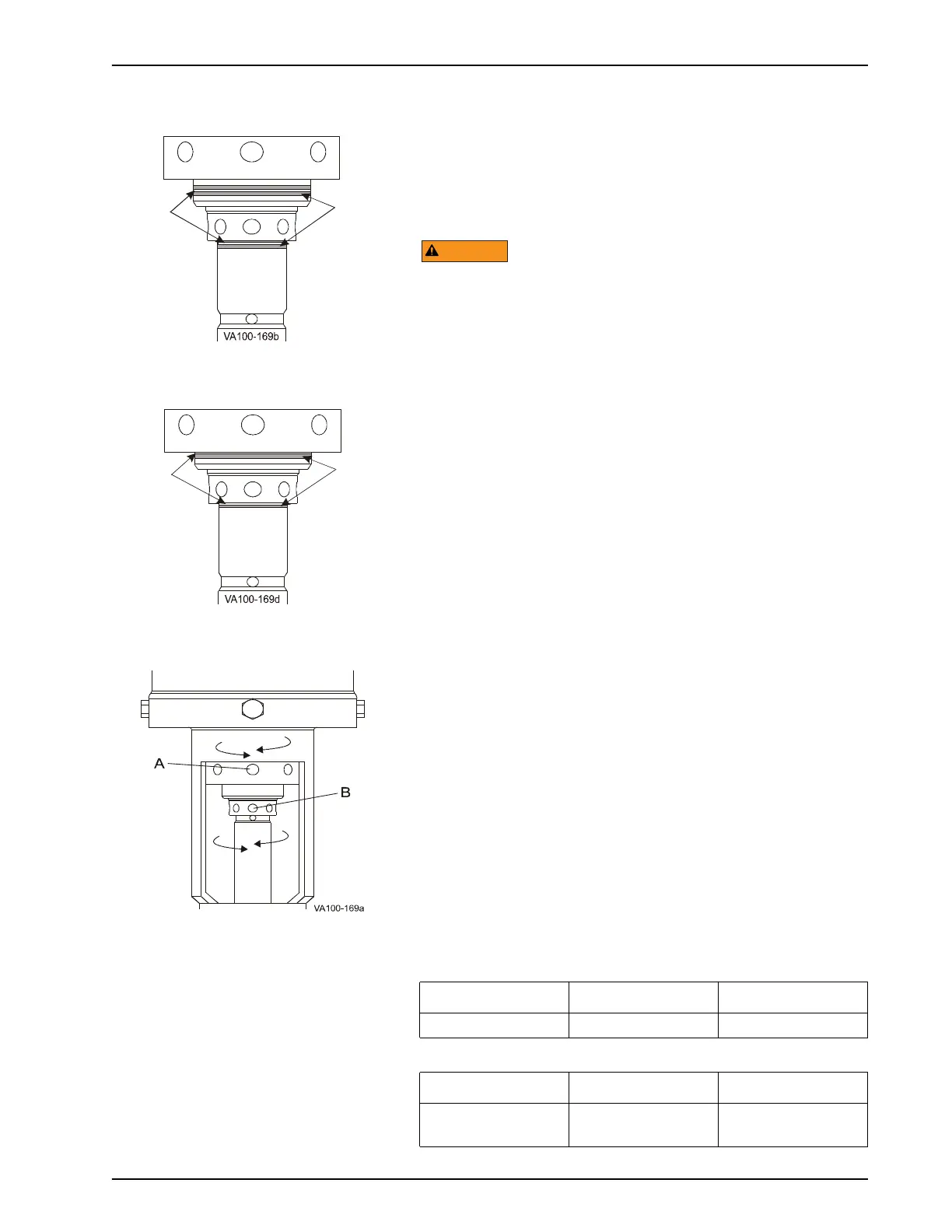
Scribe lines (item A) within the acid-etched adjustment zone (item
B) provide a visual indication of the correct factory-set
adjustment. Screw the adjusting sleeve and adjusting nut until the
bottom edges align with the scribe line as shown in Figure 18,
item A.
NOTE: Always adjust the lower seat clean first.
Do not adjust the seat clean collars with pliers, vice-grips or
adjustable jaw pliers (channel locks).
If required, adjust the seat movement. With the valve closed,
using a 3/16" diameter pin spanner or Allen wrench, adjust the
movement of the seats to the factory settings or within the
adjustment zone (Figure 17 and Figure 18, item B). Once a
successful seat movement is established, clearly mark where the
bottom edges of the adjusting sleeve and adjusting nut align, to
ensure proper resetting after disassembly.
NOTE: For W72RSP valves built prior to November 2014, the
seat clean stroke is fixed at 0.12" upper and 0.28" lower. Confirm
the stroke length after proper assembly; tighten both stems
clockwise until they are stopped metal-to-metal.
Lower seat
Operate the lower seat clean cycle multiple times. Observe the
indicator stem movement at the top of the actuator, or at the
balancer on the bottom of the valve.
To adjust the movement of the lower seat for cleaning, rotate the
adjusting sleeve in the yoke (Figure 19, item B):
• W71/W73: Rotate right to increase; left to decrease.
• W72RS: Rotate left to increase; right to decrease. See also
“W72RS Lower Stem Measurement” on page 26.
Upper seat
Operate the upper lift cycle multiple times. Observe the outer
stem movement by watching the adjusting nut in the yoke (Figure
19, item A).
• To adjust the movement of the upper seat, rotate the
adjusting nut (Figure 19, item A) left to increase; right to
decrease.
Figure 17 - Adjustment zones
with scribe lines
Figure 18 - Bottom edges align
with scribe lines
A. Adjusting nut, upper seat
B. Adjusting nut, lower seat
Figure 19 - Location of Adjusting Nut
Table 4: Proper Seat Movement: W71/W73
Valve Size Lower Seat Upper Seat
1-1/2" - 4" 1/16" (1.59 mm) 1/16" (1.59 mm)
Table 5: P
roper Seat Movement: W72RS
Valve Size Lower Seat Upper Seat
1-1/2" and 2"
2-1/2" - 4"
1/8" (3.175 mm)
1/4"(6.35 mm)
1/8" (3.175 mm)
 Loading...