Waukesha Cherry-Burrell
®
Brand W70 Series Mix Proof Valves Maintenance
10/2023 95-03087 Page 27
Disassembly of Valve
Stems
Disassembly of the valve stems is required for seat ring
replacement. (For ”Reassembly of Valve Stems‚" turn to
page 39.)
NOTE: (For seat lifting valves) Before disassembly, note the
position of the upper and lower seat lifting adjustment nuts. See
Figure 19 on page 25.
NOTE: Seals, seal grooves, and contact surfaces are precision
parts and must not be damaged.
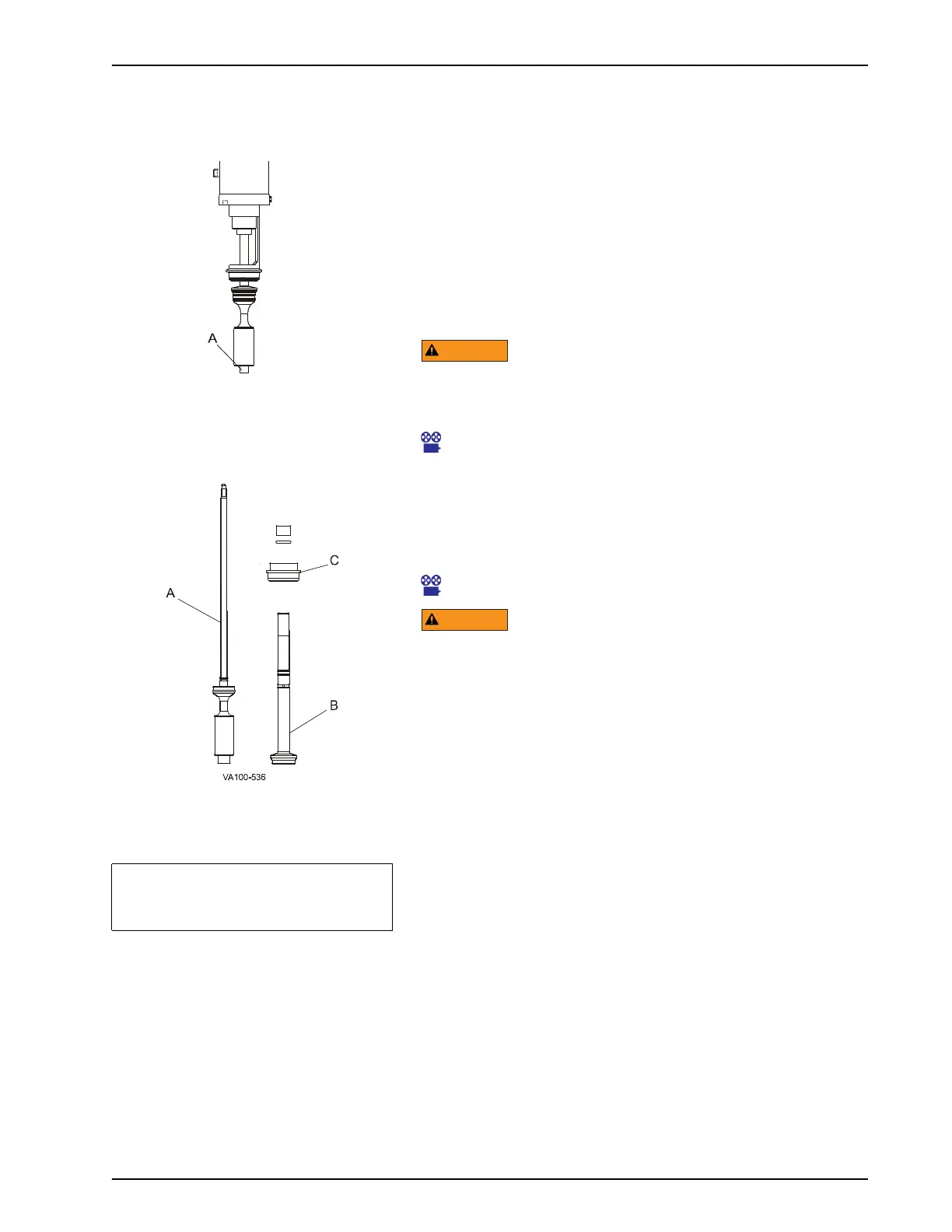
1. Lower stem removal: Using an open end wrench, remove the
lower stem (Figure 22, item A) from the actuator by turning it
counter-clockwise.
Handle the lower stem with care to prevent bending the inner
stem. A bent inner stem will cause the valve to operate
incorrectly.
Maintenance Video 3: Remove lower stem
2. Upper stem removal: Hold the adjusting sleeve stationary
with a spanner wrench, turn the stem (Figure 23, item B)
counter-clockwise, and remove it from the actuator. If the
adapter (Figure 23, item C) comes out of the yoke, handle it
with care.
Maintenance Video 5: Remove upper stem
Do not pressurize the actuator with the stems removed, as
internal O-ring damage will result.
Figure 22 - Valve Stem Removal
Figure 23 - Stem Removal
Table 6: Key for Figure 23
A = Lower Stem
B = Upper Stem
C =
Upper Adapter (Bonnet)
 Loading...