Waukesha Cherry-Burrell
®
Brand W70 Series Mix Proof Valves Maintenance
10/2023 95-03087 Page 37
Removal of O-rings and Bearings, Seat Lifting
Actuators
NOTE: For larger drawings and complete part lists, see “W71/
W73 Seat Lift Actuator” on page 82 and “W72RS/W72RSP Seat
Lift Actuator” on page 86.
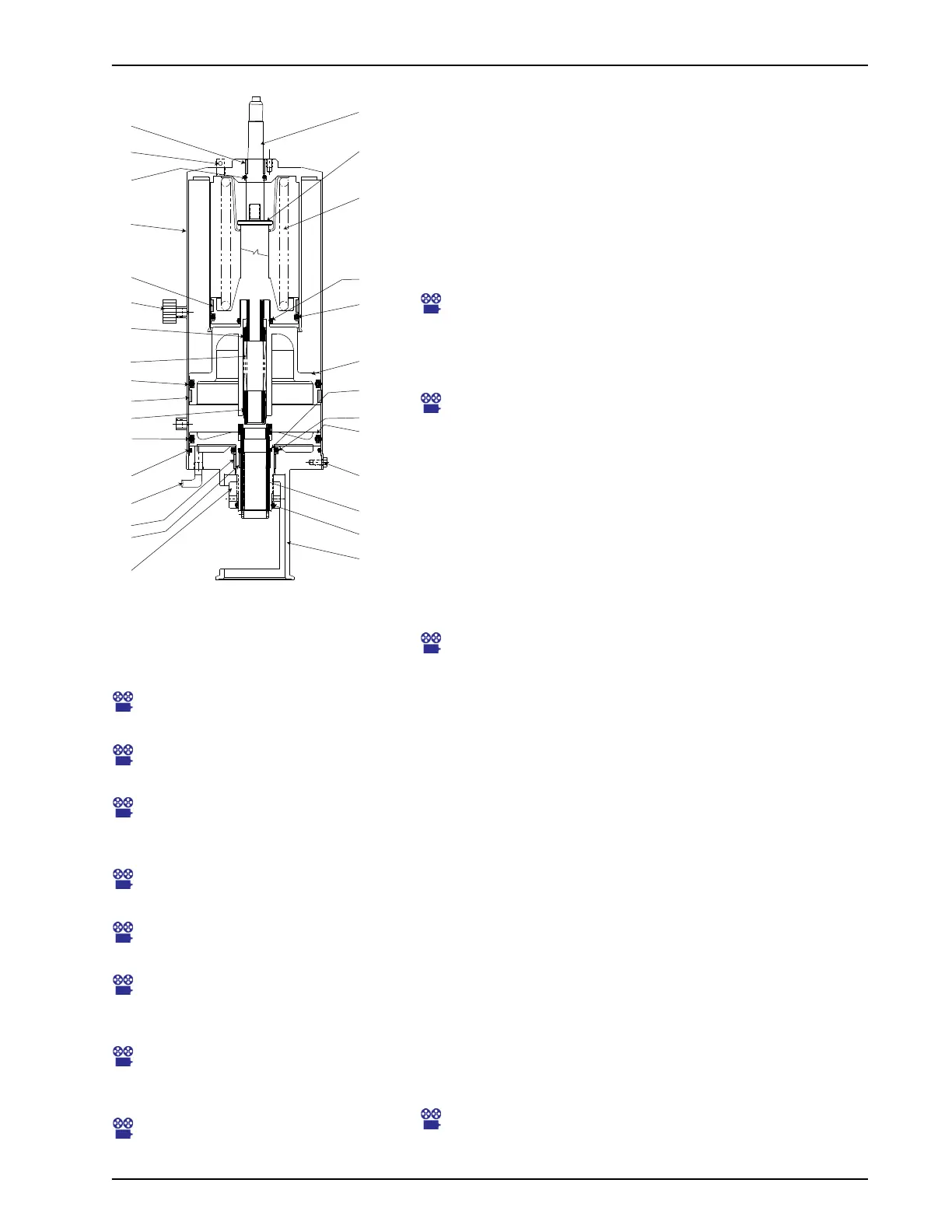
1. For seat lifting valves, remove the cap screws (Figure 36,
item 9) and remove the lower cartridge (yoke, item 12;
adjusting nut, item 20; adjusting sleeve, item 24; and upper
seat piston, item 23).
Maintenance Video 14: Actuator disassembly; lower
cartridge removal
2. To disassemble the cartridge, remove the adjusting nut (item
20) and separate the parts.
Maintenance Video 15: Adjusting Nut removal
3. Remove the small spring (Figure 36, item 18). On W71/W73
valves, also remove the bushing (Figure 35, item 28).
4. Pull out the upper cartridge (main piston, item 22; lower seat
spring and piston, item 10), by carefully threading in the lower
stem to pull it. Do not bend the lower stem.
Alternate method: Flip the canister right-side up and gently
tap it on the table (or push down the indicator stem) until the
air vacuum releases and the upper cartridge slides out the
open end.
Maintenance Video 16: Removal of main piston, lower seat
lift piston
5. Inspect the nine O-rings (Figure 36, items 6, 7, 8, 11, 17, 25,
26, and 29) and replace them if they are worn or damaged.
6. Inspect the five bearings on W71/W73 (Figure 36, items 5,
14, 15, 16, and 21) or four bearings on W72RS actuators
(items 5, 14, 15, and 16). If the bearing does not extend
slightly above the edge of the metal surface, replace it.
7. The bearing is split to allow its removal from the groove.
Place a screwdriver or pick behind the bearing and pry it
away from the wall of the yoke. A needle-nose pliers can be
used to grip the bearing for removal.
NOTE: The bearing will be damaged during removal and must be
replaced with a new bearing.
8. Assemble the stack components as shown. Make sure that
the upper cartridge components are fully inserted. Install the
yoke and adjustment nut.
NOTE: Installation of the piston and spring assembly on 4"
actuators requires a special sleeve to contain the bearing on the
piston while installing the assembly. See Figure 37 and Figure 38
on page 38.
Maintenance Video 22: Using insertion sleeve for W71/W73
Actuators
Figure 36 - W71/W73 Actuator Assem-
bly (Seat Lift Valve)
VA100-429
5
13
4
21
19
18
8
14
8
7
16
15
20
12
26
9
23
17
11
22
10
1,1a
25
29
30
6
31
24
28
33
Maintenance Video 17: Main piston
O-ring removal
Maintenance Video 18: Main piston
O-ring replacement with bearing
Maintenance Video 19: Can top
bearing and O-ring; removal and
replacement
Maintenance Video 20: Main piston
bearing
Maintenance Video 21: Lower seat
lift piston reassembly
Maintenance Video 23: Reassembly
of actuator: spacers and inner
spring
Maintenance Video 24: Reassembly
of lower cartridge O-rings and
bearings
Maintenance Video 25: Re-
installation of lower cartridge

 Loading...