Installation Waukesha Cherry-Burrell
®
Brand W70 Series Mix Proof Valves
Page 12 95-03087 10/2023
Installation
When installing the valve, ensure that no foreign materials (e.g.
tools, screws, welding wire, lubricants, cloths, etc.) are enclosed
in the system.
Location
The valve must be in a vertical position to ensure that the vent/
drain outlet system functions properly.
The vent/drain outlet at the bottom of the Mix Proof valve must
not be obstructed. The unrestricted vent/drain outlet must allow
leakages and cleaning/rinsing/sterilization fluids to go to
atmosphere in order to guarantee mix proof safe separation. If
hoses, pipes, or other components are mounted to the vent/drain
outlet to prevent splashing of leakage and cleaning/rinsing/
sterilization fluids, then they must be designed such that the fluids
flow freely to atmosphere.
Locate the valve for easy access for inspection.
Ensure that the valves and pipe systems drain properly. The two-
piece body option enables the positions of the connections to be
adjusted in relation to each other.
Welding Instructions
Prior to installing, thoroughly inspect each valve. When using
buttweld two-piece body valves, clamp connections must be used
on either the upper or lower body to allow for servicing of the O-
ring seal between the bodies. This does not apply to single-piece
bodies.
Mix Proof valves with welded connections require the following to
be performed before installation:
• Prior to installation, remove the stem actuator assembly and
lower bearing carrier.
• Remove all seals from the body.
• Weld the body into position, ensuring that the connection is
free of tension and distortion.
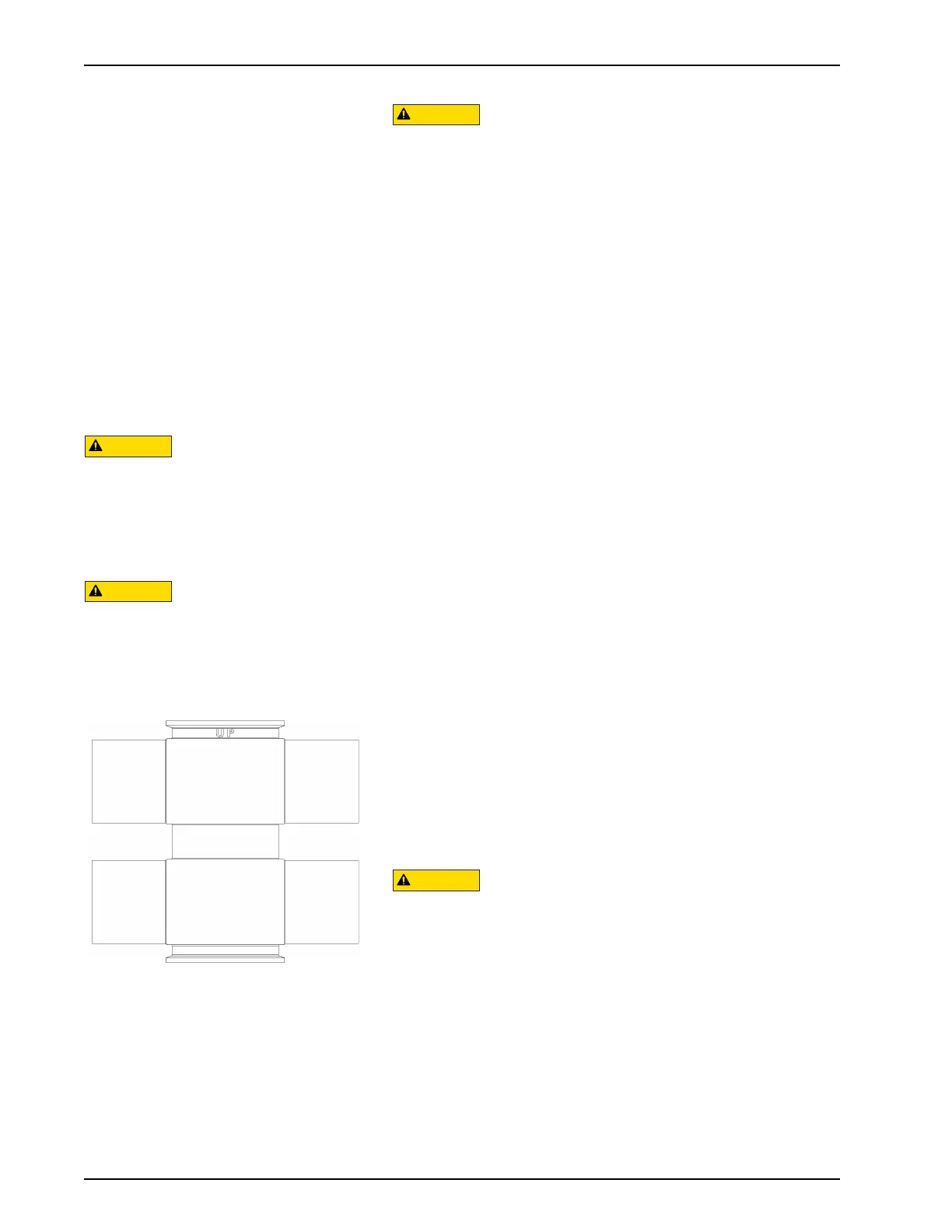
NOTE: Orient the valve so that the “UP” inscription (near the
adapter-to-body connection) is pointed toward the actuator. See
Figure 1.
Welding must be carried out by qualified personnel.
For manifold welding, fixture tables are recommended. Matrix
manifold welding requires a controlled deliberate process to
maintain the alignment of the parts.
Air Supply
Install the valves using dry, filtered air. Lubrication is not required.
If using lubricated air, refer to the solenoid manufacturer’s
specifications. The air supply must be 75 to 90 psi (5.2 to 6.2
bar).
Flow Direction
The valves should be installed to close against the flow to prevent
water hammer.
Isolate products away from the valve
prior to performing maintenance.
Before attempting to buttweld an
automatic valve into a line, disassemble
the body from the actuator. Dissipate
heat away from the valve body to
prevent warping.
Figure 1 - Valve orientation

 Loading...