Maintenance Waukesha Cherry-Burrell
®
Brand W70 Series Mix Proof Valves
Page 26 95-03087 10/2023
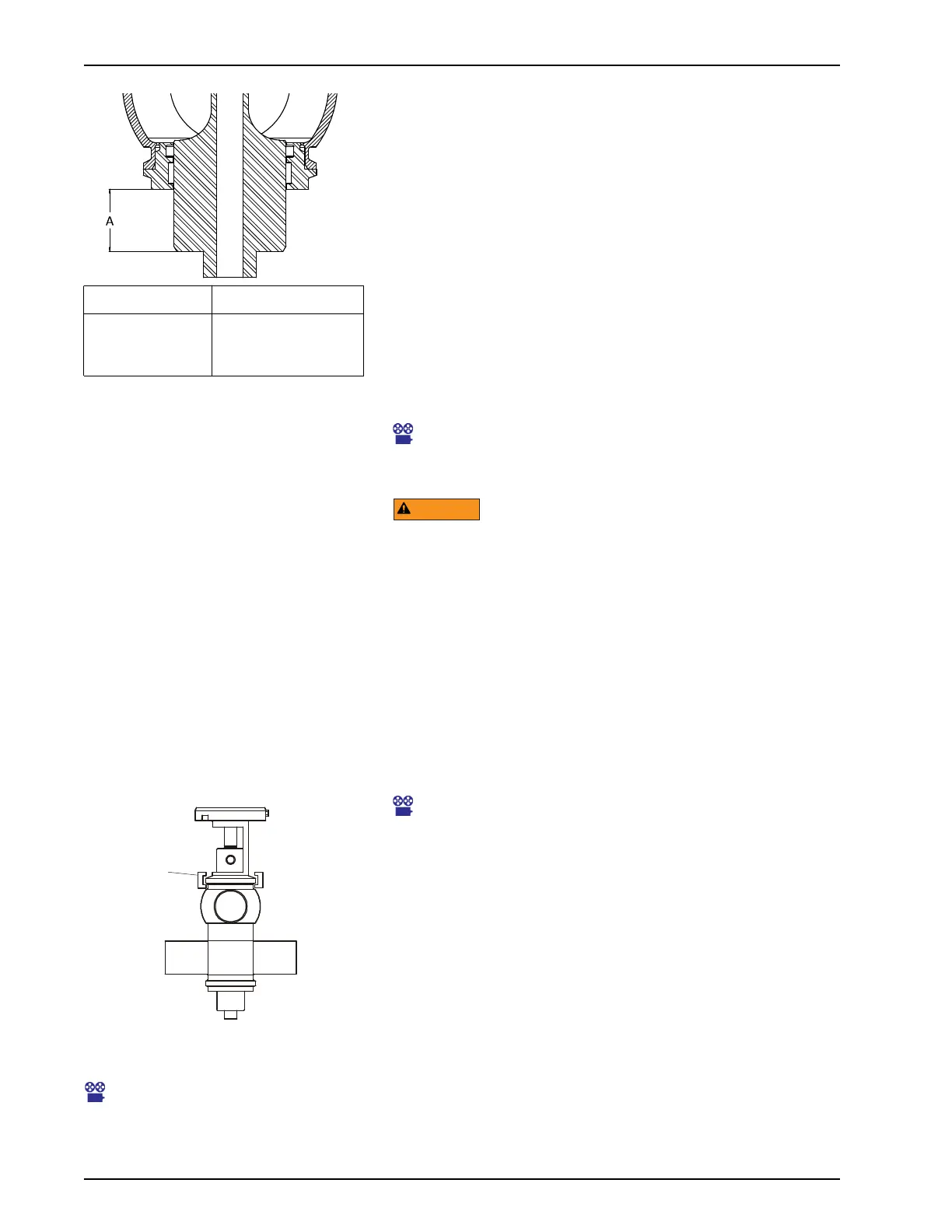
W72RS Lower Stem Measurement
For the W72RS models, the location of the lower stem is more
critical than the stem travel. Confirm the proper location of the
lower stem by measuring the distance from the lower seal
retainer to the lower shoulder of the stem (Figure 20, dimension
“A”) when the valve is static.
• To increase this measurement distance and allow more
cleaning of the lower seat, turn the adjustment sleeve to the
left.
• To decrease the distance and allow less cleaning of the lower
seat, turn the adjustment sleeve to the right.
Removing Valve from
System
This icon indicates a link to a maintenance video available
online. To access the PDF online, go to: www.spxflow.com/
en/assets/pdf/95-03087_w70mixproofv_wcb.pdf.
NOTE: If the valve has a control module
with a solenoid, the air and electric can
remain ON to assist with removal of the
valve from the body.
NOTE: On seat lifting model valves,
clearly mark on the other stem and
adjusting threads where the bottom
edges of the adjusting sleeve and
adjusting nut align to ensure proper
resetting of seat movements after
disassembly.
1. Clean, rinse, and drain the pipe system elements attached to
the valve. Remove or block the fluid and gas lines to prevent
material from entering the pipe system elements attached to
the valve. If present, disconnect the flush water supply
connection. If supplied, seat lifts can be used to check for
pressurization of the pipeline.
2. Disconnect the external flush if used.
3. Supply air to open the valve.
4. Remove the clamp between the yoke and the adapter (Figure
21, item A).
Maintenance Video 1: Remove valve from body
5. Remove the air pressure to cycle the valve closed, lifting the
valve approximately 3/8" (9.5 mm) out of the body. Shut off
and disconnect the air supply.
6. Disconnect and lock out electrical power to the valve.
7. Lift the complete valve actuator and stems out of the valve
body, being careful not to damage the stems or internals.
8. Move the valve to a work station.
9. Re-install in reverse order. Keep in mind that air must be
applied to cycle the valve open and lower the valve insert
approximately 3/8'', in order to completely reseat the valve in
the body.
Maintenance Video 2: Re-install
valve into body
10. Re-fasten the clamp between the yoke and the adapter
(Figure 21, item A), then remove the air pressure to cycle the
valve closed.
W72RS Size Dim. “A”
2"
2-1/2" and 3"
4"
1-1/3" (33.87 mm)
1-3/4" (44.45 mm)
2-1/8" (53.98 mm)
Figure 20 - W72RS Lower Stem
Before removing the actuator/valve stem assembly from the valve
body, drain all product lines connected to the body.
Figure 21 - Location of Adapter Clamp

 Loading...