Waukesha Cherry-Burrell
®
Brand W70 Series Mix Proof Valves Installation
10/2023 95-03087 Page 15
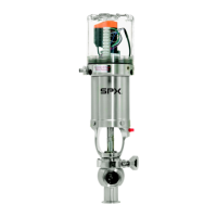
Connect the cavity cleaning supply to a suitable liquid supply to
flush the vent/drain (Figure 7) during the operation of the
processing system.
The flush supply line can be connected to the pipe system by 1/4"
(6 mm) rigid or poly flow tubing. The flush supply is blocked when
the valve is open.
Connect the supply line to the adapter connection with poly flow
tubing (Figure 7).
During CIP cleaning and valve opening (W71/W73), fluid escapes
from the drain port. Drain this off to prevent a possible hazard to
personnel.
Regulate the flush supply (Figure 7, item A) for pressures of 30
psi minimum, 50 psi maximum.
The maximum solution temperature is 180°F (60°C).
Cavity cleaning operation must fall within the fail-safe control sys-
tem. See “Cleaning” on page 23.
Take proper precaution to safeguard the flush water supply, such
as installing backflow prevention devices.
External Flush - Steam
Vent Cavity
Steam Vent Cavity, Upper and Lower Stem
Use both Upper Stem Steam Flush Adapter and Lower Stem
Steam Adapter.
This option allows continuous steaming of the vent cavity (in both
open and closed positions), upper and lower stems.
Valves equipped with the steam flush option for stem and vent
cavity can produce high temperatures and steam hazards that
may result in personal injury or death.
To steam flush the upper and/or lower stem as well as the vent
cavity, the Mix Proof Valve must be ordered with the Steam Flush
for stem and vent cavity. This option (See Figure 9 on page 16)
contains the following components:
• External flush connection, 1/4" NPT.
• Modified adapter with removed O-rings to flush the stem.
• Jacket with 1/4" Tube (S.S.) on lower balancer to flush the
lower stem (balancer).
• EPDM gaskets for all seals in the wetted area.
Figure 7 - Connection of Flush Supply
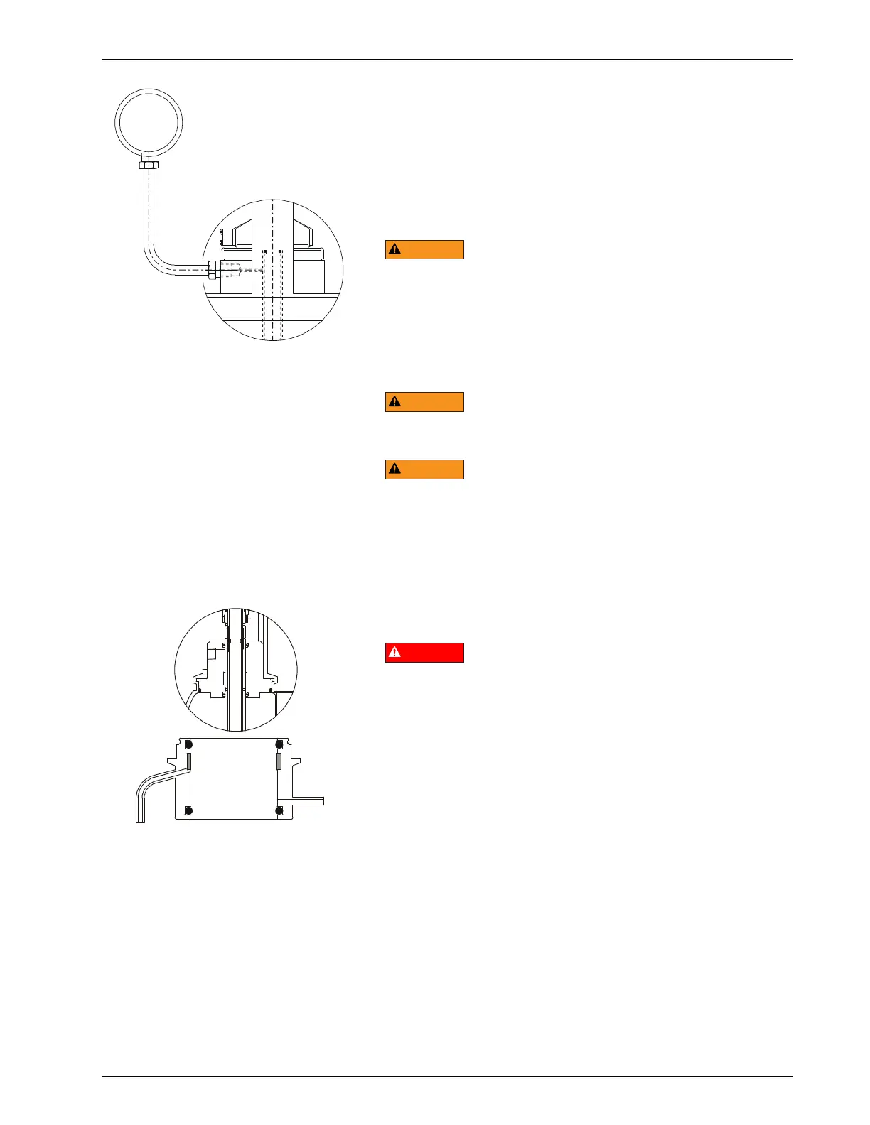
Figure 8 - External Steam Barrier -
upper stem

 Loading...