Waukesha Cherry-Burrell Installation
10/2010 95-03009 Page 27
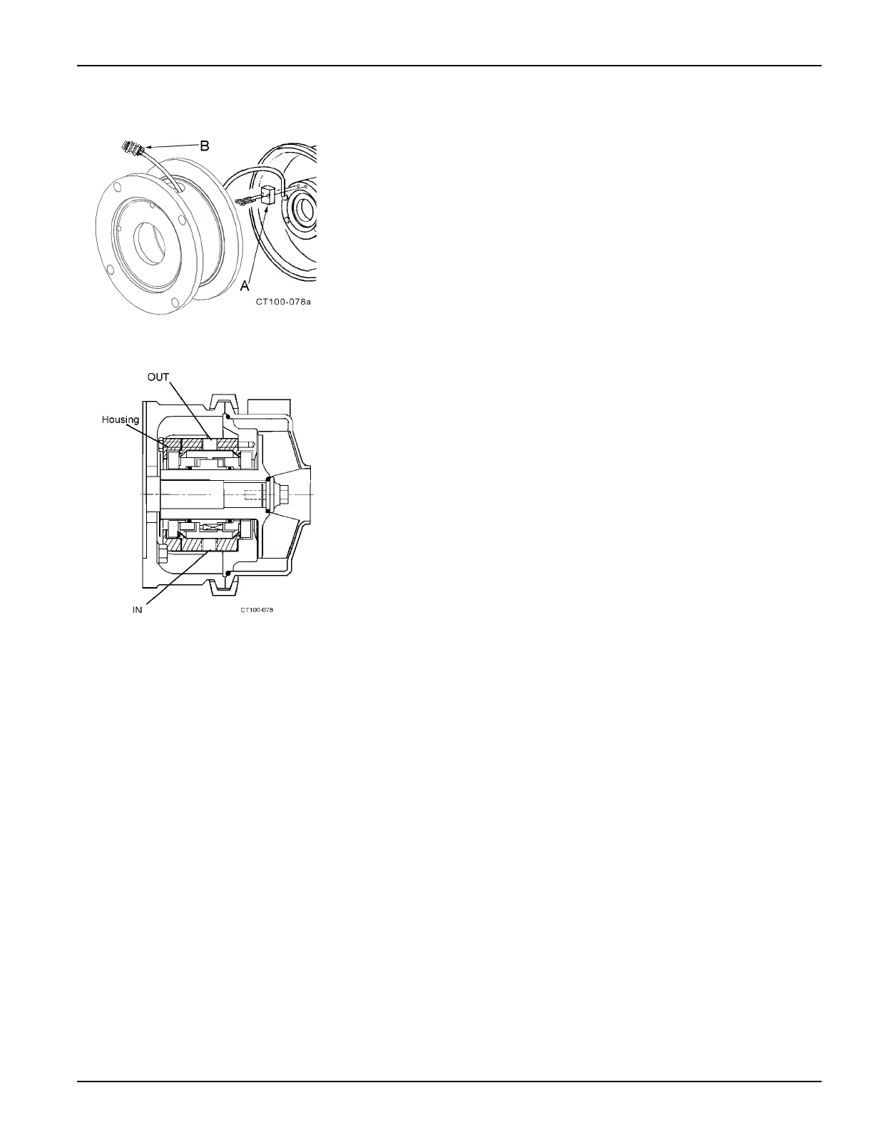
Flush Seal Option When this option is ordered, a fitting assembly (Figure 19, item A) is sup-
plied for directing a flow of water onto the backplate/seal area.
• The water cascade block must be above the seal on the assembled
backplate to flow water onto the seal face.
• The connection (Figure 19, item B) is 1/4 inch O.D. tubing.
• The required flow is approximately 5 U.S. gallons per hour.
• The recommended water supply is cool and filtered. If the product
solid
ifie
s at a cool temperature, warm or hot water can be used.
NOTE: To prevent hose contact with the rotating shaft and seal parts dur-
in
g operation, pull the excess hose to the outside of the adapter.
Type 4 Seal (Double mechanical with flush)
Attach the seal flush supply to the bottom 1/4-inch pipe-threaded hole in
the flush housing. The drain tubing attached to the top hole allows moder-
ate pressure to be supplied to the seals and allows continuous flooding.
(Figure 20).
Figure 19 - Cascade System Installation
Figure 20 - Type 4 Flush Housing