Maintenance Waukesha Cherry-Burrell
Page 34 95-03009 10/2010
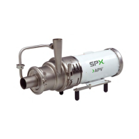
10. Remove the four 1/4" hex bolts and stationary seat retainer ring (Fig-
ure 27, items A and B).
11. Pull the stationary seal and L-gasket out of the backplate (Figure 27,
items C and D).
NOTE: The stationary se
al is brittle. Prying or hammering on the seal
plate can shatter the seal. If the stationary seal cannot be removed by
hand, place a 2-1/4 inch diameter plastic or wood rod on the impeller side
of the seal and apply even pressure to dislodge the seal.
Inspect Parts
Once disassembly is complete, perform the following inspections:
• Examine all seal surfaces and replace seals that are scratched,
crac
ked and/or braised.
• Inspect all o-rings and o-ring seats for abrasions, cuts or other wear
that
could cause leakage.
• Clean all seat areas and alignment surfaces.
NOTE: Stationa
ry seals are reversible. Use both sides before replacing
them.
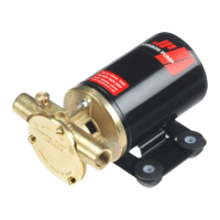
NOTE: Replace the rotary seal when the seal face extends less than 1/32
inch
(1 mm) from the body (Figure 28).
Assembly of Pump With a
Type 1 Seal
Backplate Assembly
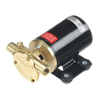
1. Lightly lubricate both sides of the L-gasket (Figure 29, item D) with a
sanitary lubricant and insert it into the backplate seal cavity.
2. Place the stationary seal into the L-ga
sket (Figure 29, items C and D).
3. Place the seat retainer over the stationary seal and secure the
re
tainer with four 1/4-20 x 1/2 inch hex head cap screws (Figure 29,
items B and A).
4. Tighten the cap screws evenly.
Figure 27 - Removing Stationary Seal
Figure 28 - Rotary Seal Replacement
Minimum
Figure 29 - Stationary Seal Assembly